


Modelle & Konfigurationen
| Modell | Lieferumfang | Typische Ausstattung |
|---|---|---|
| LS-7V4JK10000 | Gehäuse aus Aluminiumlegierung + Schutzabdeckung + PV-Panel | Solarunterstützte Stromplattform für Niedrig-/Mittellast-Nutzlasten |
| LS-7V4JK10100 | PV-Panel + CT Energiegewinnung | Bessere Betriebszeit für Freileitungsüberwachung in variablen Lastkorridoren |
| LS-7V4JK10110 | PV + CT + Power Pickup Board | Für Projekte mit größerer Ein-/Ausgangsflexibilität |
| LS-7V4JK11110 | PV + Power Pickup Board + Li-Batterie 7,4V 10Ah | Für erweiterte Autonomieanforderungen bei Verteilnetz-Überwachungsknoten |
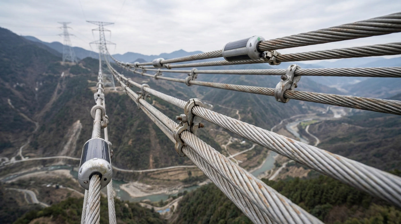
Wichtige Spezifikationen
| Artikel | Spezifikation |
|---|---|
| Produktname | Freileitungs-Stromplattform (Selbstversorgende Plattform zur Überwachung von Nutzlasten) |
| Modell | LS-7V4JK Serie |
| Anwendung | 35kV und höher Freileitungen |
| Stromeingänge | CT Energiegewinnung + Solar (Dualeingang, konfigurationsabhängig) |
| CT-Ausgang (typisch) | Ausgangsspannung 8,4V einstellbar (±3%); Stromausgang 10A, Ausgangsleistung >1,5W |
| Solarmodul (typisch) | Standardleistung 6,2W (±5%); Nennarbeits-spannung 12V (±10%); Wirkungsgrad 22% |
| Batterie (typische Option) | Nennspannung 7,4V; Kapazität 10Ah (modellabhängig) |
| Power Pickup Board (Option) | Externer Eingang 8V–75V; Ausgang 5V–24V |
| Konnektivitätsunterstützung | 4G / GPS (BeiDou) / 2,4G (unterstützt) |
| Montage | Aufsteck-Design; Leiterdurchmesser 23–40mm; Klemmkraft seitlich >50N |
| Schutzart | IP66 |
| Betriebstemperatur | -40°C bis +85°C |
| Feuchtigkeit | 1%–100% |
| Material | Gehäuse aus Aluminiumlegierung |
| Gewicht | <5kg |
| Abmessungen | Länge 335mm; Hauptdurchmesser 170mm; Nebendurchmesser 138mm |
| CT Energie-Referenz | Primärstrom 5A >0,35W / 10A >1,50W / 20A >4,00W (Testlast 400Ω) |
| Batteriepack-Platz | Batteriepack kann angepasst werden (bis zu 8×18650 Zellen) |
Kundenspezifische Integration
- Ausgangsspannung & geregeltes DC-Design abgestimmt auf Ihre Nutzlast
- Anschluss- & Kabelbaum-Anpassung
- Mechanische Montageanpassung für verschiedene Leitergrößen
- Branding / Kennzeichnung für Versorgungsprojekte
Pilotunterstützung: Geben Sie Ihr Nutzlast-Leistungsprofil + Berichtsintervall an; wir liefern eine empfohlene Konfiguration für Ihren Stromleitungsüberwachungsknoten.
