
Warum Energie die schwache Stelle in der Netzüberwachung ist
Moderne Versorgungsunternehmen investieren in Sensoren und Analytik, aber in abgelegenen Gebieten ist der erste Ausfall oft der Strom. Nur mit Batterien betriebene Systeme erfordern wiederholte Turmsteigaktionen. Das Hinzufügen einer zusätzlichen Niederspannungsleitung ist langsam und teuer. Wenn Stürme auftreten, ist das Gerät, das eine Echtzeitwarnung senden sollte, oft das erste, das offline geht.
Deshalb behandeln moderne Lösungen zur Überwachung von Versorgungsunternehmen und Stromnetzen zunehmend Strom als einen zentralen Bestandteil der Systemarchitektur—nicht als nachträglichen Gedanken.
Was ein Power Line Monitoring System typischerweise umfasst
Wenn Kunden nach Stromleitungsüberwachungssystem suchen, meinen sie normalerweise einen vollständigen Stapel:
Edge-Geräte an der Leitung
Überwachungssensoren zur Fehlererkennung, Wellenformaufnahme, Lastüberwachung und manchmal zur Überwachung der Leiter-Temperatur.
Kommunikation & Rückkanal
Mobilfunk-/Mesh-/LPWAN-Verbindungen von Leitungsgeräten zu einer Zentrale oder Cloud-Plattform.
Visuelle Anzeigeplattform & Analytik
Eine Plattform, die Ereignisse in umsetzbare Alarme und Arbeitsabläufe umwandelt (Fehlerortung, Risikoalarmierung, Wartungsplanung).
Wo LinkSolar passt: Wir bieten die Stromversorgungsschicht, die diese Edge-Geräte an Überheadleitungen am Leben erhält – damit Ihre Daten zur Überwachung von Überheadleitungen und Verteilungsnetzwerken kontinuierlich bleiben.
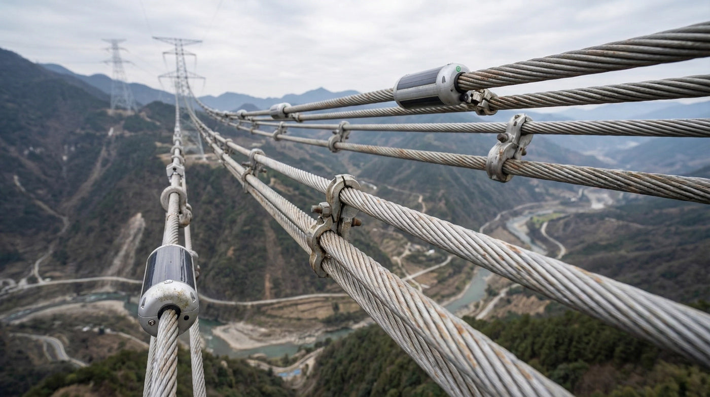
LinkSolar Oberleitungs-Stromversorgungssystem
Das System von LinkSolar wird direkt am Leiter montiert und kombiniert:
- Netzstromabgriff (Energieerzeugung) vom Leiter über einen integrierten Stromtransformator
- Gebogenes Solarmodul für zusätzliche Energie in Niedrigstrom- oder Niedriglastphasen
- Interne Li-Ionen-Batterie + geregelte Gleichstromausgabe, um stabilen Niederspannungsstrom Tag und Nacht bereitzustellen
Energieerzeugung für autonome Oberleitungsgeräte ist eine bewährte Richtung in der Industrie und Forschung, da sie die Abhängigkeit von Batteriewechseln und fehlender Infrastruktur verringert.
Empfohlene Geräte (35kV+)
| Produkt/Modell | Typische Verwendung im System | Power-Methode | Batterie | Kommunikation | Schlüsselüberwachung / Funktionen | Größe / Gewicht |
|---|---|---|---|---|---|---|
JK Oberleitungsstromplattform (LS-7V4JK-Serie) | Selbstbetriebsfähige Plattform zur Aufrechterhaltung der Online-Verbindung von Liniengeräten (Fehlerdiagnose / Eisbildung / galoppierende Knoten, Gateways usw.) | CT Energieerfassung + Solar (Dual-Eingang); optionale Stromabnehmerplatine | Konfigurationsabhängig | Unterstützt 4G, GPS/BeiDou, 2.4G | Regulierte Gleichstromausgabe für nachgelagerte Last; Klemmmontage für Leiter Ø23–40mm | 335mm Länge; <5kg |
WD Überwachungsgerät für das Galoppieren (LS-3V7WD11010) | Überwachung des Gallopierens von Leitern + verwandte Zustandsanzeigen (für die Überwachung von Übertragungsleitungen) | Solarbetriebene (eingebaute wiederaufladbare Batterie) | 3.7V 6Ah (bis zu ~30 Tage Standby bei 5-minütiger Berichterstattung ohne Aufladung) | LoRa-basierte, energieeffiziente drahtlose Verbindung; max. TX 22dBm, bis zu 500m im Freifeld; kann über ein Empfangsmodul mit RS485 verbunden werden | Galoppierende Amplitude & Frequenz, Leitertemperatur, Umgebungstemperatur/-feuchtigkeit; konfigurierbare Schwellenwerte & Warnungen | Ø98mm × 200mm; ≤2kg |
GB Eisüberwachung “Ice Sprite” (LS-9V6GB11110) | Überwachungssystem für die Beschichtung + Videoüberwachung für den Linienkorridor; Fernalarm zur Plattform | AC-Induktion (Netzenergie) + Solar + Hochtemperatur-Lithiumbatterie | 9,6V 14Ah | Integriertes 4G-Modul; unterstützt drahtlose Rückverbindung (4G/5G/WiFi) | KI-basierte Analyse der Eisdicke (visuell), Echtzeit-Bild-/Video-Upload; misst Leiter Temperatur & Strom; Objektiv-Anti-Frost-Heizung | Kompakte zylindrische Gehäuse; Speicher ≥128G |
* Die JK-Netzteilplattform bietet verschiedene Konfigurationsmöglichkeiten (wie: nur Solar, Solar + CT, Solar + CT + Verteilungstafel, Solar + Verteilungstafel + Batterie usw.)
Verwendete Anwendungsfälle
Überwachung von Freileitungen an Verteilungsleitungen
Strom für Fehleranzeiger, kompakte Fehlerrekorder und Leitungsensoren—damit Betreiber den Service schneller wiederherstellen und die Patrouillenzeit im gesamten Überwachungsbereich des Verteilungsnetzes reduzieren können.
Überwachung von Übertragungsleitungen bei extremen Wetterbedingungen
Unterstützung von Eisüberwachungsgeräten und Temperaturüberwachungsnoden für Leiter, die für die Zustandsüberwachung und Risikoalarme verwendet werden. Viele Eisüberwachungssysteme sind speziell für die Solar-/Batterieversorgung an Standorten von Türmen konzipiert, was den realen Einschränkungen entspricht.
Videoüberwachung von Leitungskorridoren & Waldbrandüberwachung
Stabile Gleichstromversorgung für kompakte Kameras und Edge-Geräte, wo das Verlegen von Stromleitungen unrealistisch ist—der visuelle Stream und die Alarme bleiben online, wenn das Wetterrisiko am höchsten ist.


Installation & Betrieb im Feld
Klemmgehäuse aus Aluminium
Leichtes Druckguss-Aluminiumgehäuse mit klappbarem Ober-/Unterteil und integrierter Klemmspange. Entwickelt für Leiter mit einem Durchmesser von 23–40 mm, mit einer Haltekraft von über 50 N in Querrichtung.
Elliptisches Profil mit integriertem Sonnenschutz
Die stromlinienförmige ovale Form erhöht die Sonneneinstrahlung auf der gewölbten PV-Oberfläche im Vergleich zu flachen Gehäusen. Die PV wird durch eine hochtransparente, hochfeste, vergilbungsbeständige Glasscheibe geschützt.
Robustes Design für raue Umgebungen
Vollständig abgedichtet nach IP66 mit einem Betriebstemperaturbereich von –40 bis +85 °C und einer Luftfeuchtigkeit von bis zu 100 % RH. Geeignet für alpine, Küsten-, Wüsten- und Tropenumgebungen bis zu 5500 m Höhe.

Elektrische Eigenschaften
Netzspannung: 35 kV und höher Freileitungen
Stromeingang des Stromwandlers: ausgelegt für Primärströme um 5–20 A; typische verfügbare Leistung ≥1,5 W für nachgeschaltete Schaltungen
PV-Eingang: ca. 6 W Nennleistung bei ~22 % Moduleffizienz
Batterie: 7,4 V / 10 Ah Li-Ionen-Akku für mehrtägige Autonomie
Gleichstromausgang: einstellbar um 8,4 V, um den Eingang Ihres Geräts anzupassen, mit Überspannungs- und Strombegrenzungsschutz
Wichtige Vorteile für Versorgungsunternehmen und Systemintegratoren

Anpassung und Systemintegration mit LinkSolar
LinkSolar kann die Freileitungsstromplattform als eigenständiges Produkt oder als Teil einer kompletten Überwachungslösung bereitstellen.
- Ausgangsspannung, Anschlüsse und Kabelbäume können an Ihre Sensor- und Kommunikationshardware angepasst werden.
- Wir entwerfen passende kleine Solarmodule und Halterungen, wenn an Turm montierte Geräte ebenfalls Hilfsstrom benötigen.
- Unser Ingenieurteam unterstützt bei der Strombudgetierung, der Standortgestaltung und der Planung von Pilotprojekten für Übertragungsunternehmen und Lösungsanbieter.
Häufig gestellte Fragen
Ist das nur ein Netzteil oder ein vollständiger Knoten eines Überwachungssystems für Oberleitungen?
Ist das nur ein Netzteil oder ein vollständiger Knoten eines Überwachungssystems für Oberleitungen?
Es handelt sich um einen selbstbetriebenen Überwachungsmodul für die Überwachung von Freileitungen – nicht nur um ein Strommodul. Die Einheit integriert Energiegewinnung vom Leiter (CT), ein gebogenes Solarpanel, internes Batteriemanagement und geregelte Gleichstromausgänge zur Unterstützung von Überwachungsanwendungen. Je nach Ihrem Projekt können wir es liefern als:
- Strom + Gehäuseplattform für Ihr gewähltes Sensor-/Kommunikationsmodul, oder
- Ein integrierteres Front-End-Modul, das mit Ihrer Überwachungsarchitektur des Verteilernetzes abgestimmt ist (Strom + Kabelbaum + Montage + Schnittstellenanforderungen).
Wie überwacht es online während Zeiten mit geringer Auslastung und langen Nächten?
Wie überwacht es online während Zeiten mit geringer Auslastung und langen Nächten?
Das System verwendet eine hybride Energiestrategie: Energieerfassung durch Leiter + Solarunterstützung + interne Batterie. Wenn der Leitungsstrom sinkt oder das Sonnenlicht begrenzt ist, überbrückt die Batterie die Lücke, sodass Ihre Überwachungsnutzlast online bleibt. Für Einsätze zur Versorgungsüberwachung dimensionieren wir die Konfiguration basierend auf dem durchschnittlichen/spitzen Verbrauch Ihrer Nutzlast und den erforderlichen Autonomiestunden, damit der Knoten über saisonale und Lastvariationen hinweg zuverlässig bleibt.
Wie wählen wir die richtige Ausgangsspannung und die passenden Anschlüsse für unsere Überwachungsgeräte aus?
Wie wählen wir die richtige Ausgangsspannung und die passenden Anschlüsse für unsere Überwachungsgeräte aus?
Die meisten Überwachungsstacks verwenden geregelte Gleichstromversorgung, aber die genaue Spannung und die Steckertypen variieren je nach Geräteanbieter. LinkSolar unterstützt benutzerdefinierte Ausgangsspannungen und Kabelbäume, um Ihre Überwachungshardware anzupassen, einschließlich Steckerauswahl, Polaritätsschutz und Zugentlastung für Außeninstallationen. Wenn Sie Ihr Gerätespezifikationsblatt (Spannungsbereich, Spitzenstrom, Steckertyp) bereitstellen, können wir eine sofort einsatzbereite Konfiguration vorschlagen.
Ist die Installation kompliziert? Müssen wir zusätzliche Kabel verlegen oder einen separaten Stromschrank hinzufügen?
Ist die Installation kompliziert? Müssen wir zusätzliche Kabel verlegen oder einen separaten Stromschrank hinzufügen?
Es ist keine zusätzliche Niederspannungszufuhr erforderlich. Die Einheit ist für die Überkopfinstallation konzipiert und wird in der Nähe des Standorts des Überwachungsgeräts befestigt. Dies reduziert das Graben, die Schränke an den Masten und die ständigen Batteriewechsel. Ihr Team benötigt in der Regel nur die Standardverfahren für den Zugang zu Leitungen, und wir stellen Montageanleitungen sowie grundlegende Schaltpläne für die Integration des Überwachungsgeräts zur Verfügung.
Wie validieren wir die Zuverlässigkeit vor dem vollständigen Rollout (Pilotunterstützung)?
Wie validieren wir die Zuverlässigkeit vor dem vollständigen Rollout (Pilotunterstützung)?
Wir empfehlen einen kleinen Pilotversuch an repräsentativen Futterstellen/Spannen. Wir helfen Ihnen bei der Definition: Standortauswahl, erwartete Last/Strombereiche, Lichtverhältnisse, Leistungsbudget der Geräte und Ziele für Alarm/Verfügbarkeit. Während des Pilotversuchs können Sie das kontinuierliche Verhalten der Fernüberwachung, die Batterieleistung in Worst-Case-Szenarien und die Stabilität der Echtzeit-Alarmberichterstattung überprüfen. Nach der Validierung standardisieren wir die Konfiguration für den skalierbaren Einsatz.
