Des solutions solaires sur mesure pour propulser vos projets.

Alimentation de capteurs IoT, caméras de surveillance et stations météo dans plus de 20 pays.

Du prototype à la production en série — un seul fournisseur, un seul interlocuteur.

overhead line power supply

Overhead Line Power Platform

A clamp-on power platform that combines conductor-current energy harvesting, integrated solar input, and optional battery support to provide regulated DC power for monitoring payloads on remote overhead lines.

Quick answer

The LS-7V4JK platform is the power layer for a conductor-mounted monitoring node, not the monitoring application by itself. LinkSolar selects the CT, solar, battery, regulated-output, connector, and mounting configuration from the payload voltage and current profile, reporting interval, expected minimum line current, site solar conditions, autonomy target, and conductor dimensions.

Who this solution is for

  • Utility monitoring teams

    Teams adding fault indicators, line-condition sensors, compact gateways, cameras, or other low-power payloads to overhead corridors.

  • Grid solution integrators

    Integrators that own the monitoring payload, communications, and platform workflow and need a compatible conductor-mounted power layer.

  • Remote corridor operators

    Operators of feeders, laterals, crossings, and storm-prone spans where new low-voltage feeders or frequent battery replacement are impractical.

  • Pilot and rollout programs

    Teams validating payload uptime, mounting, data delivery, and service practice before standardizing a corridor deployment.

Technical considerations

LS-7V4JK cylindrical overhead line power platform with integrated curved solar surface.

System role

Use the platform as a configurable power layer

The platform mounts around the conductor and supplies regulated DC power to a separate monitoring payload. The payload may be a fault indicator, line-condition sensor, compact gateway, positioning device, or another low-power monitoring unit, provided its electrical and mechanical requirements are reviewed.

Treat the power platform, payload, communications link, and data platform as separate integration boundaries. LinkSolar can match output regulation, connector and harness details, and the supported mechanical interface; the monitoring function, firmware, radio network, and operating workflow remain project-specific.

LS-7V4JK overhead line power platform clamped around a conductor with its integrated solar surface exposed to daylight.

Energy continuity

Combine CT harvesting, solar input, and storage around the real duty cycle

CT harvesting output changes with conductor current, while solar input changes with season, orientation, shade, and weather. An optional battery can bridge nights, low-current windows, communications peaks, and short periods of weak solar input, but it does not remove the need for an energy budget.

Final selection should use the payload's continuous, startup, transmit, and event currents; reporting behaviour; expected minimum current periods; worst-month solar conditions; temperature; conversion losses; autonomy target; and recovery time. The catalogue values on this Page are configuration references, not guaranteed site output.

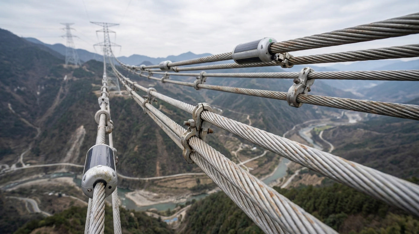
Representative overhead line monitoring devices and solar-assisted power hardware installed on conductors above a river crossing.

Installation and reliability

Verify the conductor interface and field environment before rollout

The current reference platform uses an aluminum-alloy housing and a clamp-on conductor interface. Confirm conductor diameter, clamping method, hardware retention, cable routing, payload mass, clearances, vibration, wind and ice exposure, corrosion environment, installation method, and inspection interval for the actual line.

IP66 and the published environmental values describe product-level references; they do not replace project review of the complete assembled node or the utility's live-line, outage, grounding, and work-safety procedures. LinkSolar can provide mounting and harness information for the selected configuration.

LINKSOLAR LS-7V4JK Overhead Line Power Platform

Customization boundaries

Lock the electrical and documentation interfaces before procurement

Provide the payload input-voltage range, average and peak current, startup behaviour, reporting and transmit interval, connector and cable requirements, communications equipment, expected line-current profile, conductor dimensions, environmental range, and required autonomy. These inputs determine the energy-source combination, regulated output, optional battery, power-pickup board, and harness.

Confirm drawings, model suffix, electrical limits, environmental rating, battery transport documents where applicable, labels, inspection or test records, and market-specific conformity requirements for the exact supplied configuration. A series-level Page is not evidence that every optional combination carries the same documentation.

Representative topology

Reference architecture for a conductor-mounted monitoring node

A representative node combines CT harvesting and the integrated solar input through power management and optional storage, then provides a regulated DC output to the monitoring payload. The payload sends measurements or events through the selected cellular, LPWAN, mesh, or other project-defined communications path to a utility platform, SCADA, or DMS workflow.

The selected output rail, battery option, connector, communications interface, reporting schedule, and alarm logic depend on the complete monitoring system. The platform supplies the power boundary; it does not by itself provide the sensing application, gateway service, dashboard, or control-room integration.

Electrical and system reference specifications

These values describe the current LS-7V4JK series references and options shown on the legacy Page. Confirm the exact model suffix and final interface in the quotation and approved drawing.

Electrical and system reference specifications
ItemReference value
Product and application

LS-7V4JK series overhead line power platform for monitoring payloads on overhead transmission lines rated 35 kV and above.

Power inputs

CT energy harvesting and solar input; availability depends on model and configuration.

CT output reference

8.4 V adjustable (±3%) with listed available output power greater than 1.5 W. Confirm the applicable conductor current, test condition, and exact module.

Integrated solar reference

6.2 W standard power (±5%), 12 V nominal working voltage (±10%), and listed 22% conversion efficiency.

Battery option

Listed 7.4 V, 10 Ah option; configuration-dependent. The legacy Page also states space can be customized for up to eight 18650 cells.

Power-pickup board option

Listed external input range 8–75 V and output range 5–24 V; select the exact regulated output from the payload requirements.

Payload connectivity support

The legacy Page lists 4G, GPS/BeiDou, and 2.4 GHz support. Confirm which interfaces belong to the selected payload and project scope.

CT energy test reference

Primary current 5 A: greater than 0.35 W; 10 A: greater than 1.50 W; 20 A: greater than 4.00 W, stated for a 400 Ω test load.

The legacy Page labels 10 A as an output current, while another existing LinkSolar theme reference describes approximately 5–20 A as the primary conductor-current range. The V2 draft does not publish 10 A as output current; confirm the exact datasheet and test condition before migration apply.

Mechanical and environmental reference specifications

Mechanical and environmental reference specifications
ItemReference value
Mounting

Clamp-on reference for conductor diameters 23–40 mm; listed lateral clamping force greater than 50 N.

Ingress protection

IP66 reference. Confirm the rating of the final assembled configuration and every connector and cable entry.

Operating temperature

Listed range −40 °C to +85 °C. Confirm battery and optional-component limits for the selected configuration.

Humidity

Listed 1–100% relative humidity. Confirm the test basis and condensation conditions before treating the endpoints as an operating guarantee.

Housing material

Aluminum alloy. Confirm surface treatment, fasteners, and corrosion requirements for the site.

Weight

Listed below 5 kg; exact mass depends on the selected options.

Dimensions

Listed length 335 mm, major diameter 170 mm, and minor diameter 138 mm.

Verify mechanical fit, clearances, conductor compatibility, installation method, and the exact model drawing before ordering.

Reference configurations

Typical configurations for planning reference; final sizing depends on site and load data.

Reference configurations
Scenario Reference solutionPanel and constructionExpected outcome
Solar-assisted platform for a low- or medium-duty payload

LS-7V4JK10000 combines the aluminum-alloy enclosure, protective cover, and photovoltaic input for a payload whose measured energy budget can be supported without CT harvesting.

Confirm payload voltage and current states, worst-month solar input, mounting orientation, shading, temperature, conductor interface, and the required reserve or battery strategy.A reference starting point only. Final uptime follows the measured load, site conditions, optional storage, and recovery requirement.
Hybrid solar and CT input for variable-load corridors

LS-7V4JK10100 combines the photovoltaic input with CT energy harvesting so conductor current can supplement solar energy for compatible monitoring payloads.

Review the expected minimum, normal, and peak line current alongside solar conditions and the payload duty cycle; confirm the regulated output and low-energy behaviour.A hybrid reference configuration whose contribution from each input changes with line current and site solar conditions.
Hybrid input with a configurable power-pickup board

LS-7V4JK10110 adds the optional power-pickup board to support a wider project-defined input and regulated-output interface for compatible monitoring equipment.

Lock the payload input limits, continuous and transient current, converter efficiency, cable drop, protection, connector, and harness before selecting the output rail.A reference integration class; the wider electrical range must be matched to the exact board and payload rather than treated as one fixed operating point.
Battery-supported platform for extended low-input periods

LS-7V4JK11110 is a battery-supported reference using the photovoltaic input, power-pickup board, and a listed 7.4 V, 10 Ah battery option for projects that need additional reserve.

Size usable storage from temperature, payload states, autonomy, permissible depth of discharge, charge sources, recovery time, enclosure space, transport documentation, and service interval.A listed reference option, not a guaranteed autonomy duration. Validate the final battery and energy budget for the project.

Frequently asked questions

Is the LS-7V4JK a complete monitoring system or only the power layer?

It is a conductor-mounted power platform for a separate monitoring payload. The selected configuration can provide regulated DC power from CT harvesting, solar input, and optional storage. The sensor or camera, communications link, firmware, data platform, and operating workflow must be defined as part of the complete project.

What conductor current is needed for CT harvesting?

CT contribution depends on conductor current and the exact module. The current Page lists test references above 0.35 W at 5 A, 1.50 W at 10 A, and 4.00 W at 20 A with a 400 Ω test load. Final selection should combine the expected current profile with payload measurements, solar conditions, storage, autonomy, and recovery requirements.

Can the output be matched to different monitoring devices?

Yes, within the selected power-board and system limits. The legacy Page lists an optional board with an 8–75 V external input range and 5–24 V output range. Provide the payload's voltage tolerance, continuous and peak current, startup behaviour, cable length, connector, and harness requirements so the regulated interface can be reviewed.

How is uptime handled during low-current periods or long nights?

Solar input can supplement CT harvesting when line current is low, and optional storage can bridge nights, communications peaks, and short low-input periods. Required capacity depends on the measured payload duty cycle, minimum line-current duration, worst-month solar conditions, temperature, losses, autonomy target, permissible load behaviour, and recovery time.

What conductor sizes and installation conditions must be checked?

The current reference lists a clamp-on interface for 23–40 mm conductors and lateral clamping force above 50 N. Confirm the exact conductor, clearances, payload mass, hardware retention, vibration, wind and ice exposure, corrosion, live-line or outage procedure, cable routing, access, and inspection interval with the utility before installation.

Match the power platform to your monitoring payload

Send the payload datasheet, voltage range, normal and peak current measurements, startup and transmit behaviour, reporting interval, communications method, connector and harness needs, expected minimum and normal line current, conductor diameter, environmental limits, solar and shade conditions, autonomy target, installation method, rollout quantity, and required documentation. LinkSolar will review the suitable LS-7V4JK configuration and project quotation.