Custom solar solutions that power your projects forward.

Powering IoT sensors, security cameras, and weather stations in 20+ countries.

From prototype to production — one supplier, one contact.

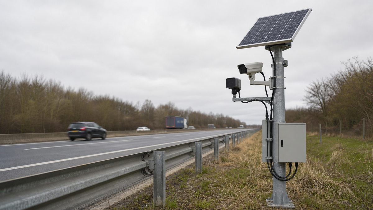
Solar-powered roadside traffic monitoring station with a panel, camera, radar sensor and weatherproof power enclosure beside a divided highway.

Solar Power for Roadside and Traffic Monitoring

Power traffic counters, ANPR cameras, road-weather sensors, and work-zone monitoring without waiting for a grid connection. LinkSolar sizes the solar, battery, enclosure, outputs, and mounting layer around continuous vibration, de-icing salt exposure, winter autonomy, and the actual roadside load schedule.

Quick answer

Roadside sites are often close to a power line they cannot practically use. Solar avoids utility applications and trenching, but the power platform must survive continuous traffic vibration, corrosive winter spray, seasonal shade, and permit-driven mounting limits. LinkSolar supplies the power and mounting layer; the road authority remains responsible for structural and right-of-way approval.

Who this solution is for

  • ITS integrators

    Teams deploying traffic counters, classifiers, ANPR cameras, travel-time sensors, and corridor communications equipment.

  • Highway and municipal agencies

    Authorities adding permanent monitoring points, road-weather stations, and work-zone systems where a new grid connection would delay deployment.

  • Work-zone contractors

    Contractors that need portable monitoring power for a project and then expect to relocate the same equipment to another site.

  • Rail and level-crossing operators

    Operators working in a similarly demanding vibration environment, with a stricter safety and availability case where the monitoring function is safety related.

Technical considerations

Close view of a roadside monitoring pole showing solar panel clamps, camera mount, sealed enclosure, cable glands and supported cable routing.

Mechanical reliability
Design every connection for continuous traffic vibration

A pole beside a live carriageway is excited by every heavy vehicle for years. The failure normally begins at a fastener, clamp, crimp, or unsupported cable loop rather than at the solar panel itself.

Specify thread-locking or locking hardware, proper crimps, strain relief, supported cable runs, and a documented clamp inspection interval before the first unit is built. A clamp that has crept only a few millimetres may be hard to see from the road but behaves differently in a gust.

Maintenance also has a traffic-management cost. The correct hardware and inspection plan reduce the number of interventions that must be performed beside an active lane.

Review pole-mounted camera bracket selection

Close view of stainless fasteners, isolation washers, galvanized bracket, anodized solar-panel frame and sealed cable entry in a winter roadside setting.

Winter corrosion

Treat de-icing salt as a coastal corrosion environment

Road spray carries de-icing salt across panels, clamps, fasteners, cable entries, and enclosures. Within the regular spray zone, A4 or AISI 316 stainless is the appropriate starting specification; A2 or AISI 304 belongs only where exposure is genuinely lower.

Isolate dissimilar metals because a stainless fastener through bare aluminium can create a galvanic cell in salty moisture. State anodizing thickness in microns rather than accepting the word anodized without a measurable requirement.

Cold conditions also reduce usable battery capacity and may restrict low-temperature charging. Size the reserve for the local winter and include salt-film cleaning or additional energy margin where road spray repeatedly soils the module.

Read the cold-climate battery field notes

Permits and scope

Confirm right-of-way and structural requirements before ordering

Road authorities govern permitted height, offset from the lane, clear-zone placement, foundations, impact behaviour, and whether a support must be breakaway. These conditions can change the pole and array layout after the electrical sizing is already complete.

LinkSolar can coordinate the panel, battery, controller, enclosure, outputs, corrosion-rated hardware, and mounting bill of materials, but does not certify a structure for roadside installation. Structural and right-of-way approval must come from the responsible authority and qualified local engineers.

Confirm those constraints before hardware is ordered. A permit condition on the pole is more likely to delay a roadside project than the manufacturing lead time of the power kit.

Field design

Size and package the platform for the actual field deployment

Assess winter shade from overpasses, sign gantries, noise barriers, and roadside vegetation rather than judging the site on a summer installation day. Add margin or cleaning access where traffic spray leaves a persistent film on the module.

Keep the modem or controller on a separate fused rail from an IR illuminator or variable message sign so a high-current burst cannot reset communications. Include surge protection because roadside poles are exposed and may be close to overhead lines.

For relocatable work-zone systems, use captive hardware, robust connectors, handling-tolerant enclosures, and tamper-resistant fasteners. Tell us at quotation stage if the kit will be moved because repeated assembly changes the preferred mechanical specification.

Reference power layout showing a solar panel, charge controller, battery, protected distribution, grounding and separate continuous and burst-load branches.

Reference architecture

A roadside power architecture that separates continuous and burst loads

A typical roadside platform combines a 60-600 W monocrystalline array, a 12 V LiFePO4 battery within a 40-300 Ah planning range, an MPPT controller, an IP65 powder-coated enclosure with controlled ventilation, and locking corrosion-rated hardware.

Use protected output branches so the continuous sensor, edge processor, or cellular link is isolated from high-current IR, sign, or heater events. Confirm peak current as well as daily watt-hours, then size the battery for the approved winter autonomy and the array for both the daytime load and reserve recovery.

The final array, battery, cable, fuse, surge, mounting, and enclosure choices depend on device datasheets, duty cycle, minimum temperature, site solar study, wind exposure, salt zone, and the road authority's structural conditions.

Review the remote solar power platform

What roadside monitoring equipment actually draws

Build the load schedule from each device's operating pattern, not from the application name. Night illumination, continuous connectivity, heaters, and display peak current are the items most often missed in an early budget.

What roadside monitoring equipment actually draws
LoadDraw patternSizing note
Inductive loop or radar counter

Low, near-continuous.

Modest and predictable; rarely the main constraint.

ANPR or classification camera

Continuous during operating hours, with IR illumination at night.

Night-time IR is frequently omitted from the first energy budget.

Edge processing unit

Continuous, rising during inference.

On-pole processing reduces uplink cost but increases the local power load.

Cellular uplink

Continuous or batched according to the system design.

An always-on link can exceed 25-30 Wh per day on its own.

Variable message sign

Burst load with high current while displaying.

Peak current and battery discharge capability can govern even when daily watt-hours are moderate.

Road-weather sensors

Low and duty-cycled unless heating is fitted.

A heated element can dominate the winter energy budget.

Use measured data where available and confirm modem state, camera illumination, inference duty cycle, heater control, and display current before the power platform is released for production.

Reference roadside power architecture

These are application planning ranges, not a substitute for a load calculation, worst-month solar study, structural review, and road-authority approval.

Reference roadside power architecture
BlockTypical planning specificationRoadside-specific purpose
Solar panel

60-600 W monocrystalline planning range.

A small counter and a continuously connected ANPR site are different energy and structural problems.

Battery

12 V LiFePO4, commonly evaluated within a 40-300 Ah planning range.

Size for the approved winter autonomy, when solar input and usable cold-temperature capacity are both lower.

Charge controller

MPPT controller matched to array voltage, battery chemistry, and current.

Improves energy recovery during the low and diffuse light that defines winter sizing.

Enclosure

IP65 powder-coated metal cabinet with sealed entries and a suitable breathable vent.

Protects electronics from traffic spray while managing condensation caused by daily temperature swings.

Protected outputs

Dual fused 12 V DC branches or device-specific protected rails.

Keeps sign, heater, or IR burst current away from the modem and continuous sensor rail.

Mounting hardware

Locking fasteners, supported cables, measurable anodizing, and corrosion-rated metal grades.

Addresses the combined vibration and salt-spray environment but does not replace local structural certification.

Final choices may sit outside these ranges when measured load, minimum temperature, poor solar access, long autonomy, display peak current, wind, corrosion exposure, or authority conditions require it.

Recommended products and kits

  • Side profile of aluminum pole mount with two hose clamps on a round pole.
    5-50 W sensor nodes

    Universal pole mount kit for small roadside nodes

    A practical mounting option for 5-50 W panels on lower-power counters, sensors, or telemetry nodes. It is not a universal structure for ANPR cameras, variable message signs, or 60-600 W integrated roadside platforms; those sites require a project-specific mount, wind review, corrosion specification, and road-authority approval.

    View the universal pole mount kit

Reference configurations

Typical configurations for planning reference; final sizing depends on site and load data.

Reference configurations
Scenario Reference solutionPanel and constructionExpected outcome
Low-power traffic counter or sensor node

A radar, inductive-loop interface, or environmental sensor with a predictable low load and a batched cellular uplink rather than a continuously streaming connection.

Often evaluated around a 60-100 W array with a modest LiFePO4 reserve, MPPT charging, protected DC output, and a vibration-tolerant 5-50 W panel mount only where the selected panel and site loads remain within its rated scope.A planning reference for modest, predictable loads. Final sizing still follows worst-month solar input, telemetry behaviour, winter temperature, shade, autonomy, and local structural approval.
ANPR or classification camera with cellular uplink

A camera, night IR illuminator, edge processor, and continuously connected cellular modem. Night-time illumination and inference load must be present in the energy and peak-current budget.

Commonly evaluated within a 200-600 W array range with a substantially larger LiFePO4 bank, MPPT controller, IP65 power enclosure, separate fused rails, surge protection, and project-specific pole hardware.Prevents IR or processing peaks from resetting the communications rail and keeps the winter reserve visible as an explicit design target rather than an unspecified safety factor.
Relocatable work-zone monitoring platform

A temporary camera, counter, radar, or sign system that will be assembled, transported, and commissioned at more than one site during its service life.

Size within the 60-600 W application range from the actual load, then add captive hardware, durable connectors, tamper-resistant fasteners, supported cables, and an enclosure designed for repeated handling and transport.A reusable power platform whose mechanical specification reflects relocation from the start. Each new site still requires a solar, wind, placement, and authority review.

Frequently asked questions

How much solar power does a roadside traffic monitoring site need?

It depends more on the device than the roadside label. A radar or loop counter with a batched uplink may be evaluated around 60-100 W with a modest battery. An ANPR camera with night IR, edge processing, and a continuous cellular link commonly enters a 200-600 W array range with a larger bank. Size from 24-hour watt-hours in the worst month and include illumination, heating, conversion loss, and autonomy from the start.

Why use solar when the site is close to a power line?

A connection may still require a utility application, trenching near or under a carriageway, traffic management, and a permit process that lasts longer than the monitoring project. Solar is often chosen for deployment speed and access, especially for work zones and temporary installations, rather than only for energy independence.

Does traffic vibration really damage roadside solar hardware?

Yes. Fasteners can work loose without locking hardware, clamps can creep, and poorly supported crimps or connectors can fatigue before the cable itself. Specify locking hardware, proper strain relief, supported cable, and an inspection schedule before installation because retrofitting beside a live carriageway is expensive.

What stainless grade should roadside hardware use?

Where de-icing salt reaches the site, use a coastal-style starting point: A4 or AISI 316 within the spray zone and A2 or AISI 304 only where exposure is genuinely lower. Isolate dissimilar metals, because a stainless bolt through bare aluminium in salty moisture accelerates corrosion of the aluminium. Final material selection belongs in the project corrosion specification.

Can the same solar kit move between work zones?

Yes, if repeated assembly is part of the approved specification. Captive hardware, robust connectors, handling-tolerant enclosures, supported cables, and tamper-resistant fasteners become more important. Each new location still needs its own solar, shade, wind, placement, and authority review.

Plan the power layer for your roadside monitoring site

Send the device datasheets, average and peak loads, operating schedule, night-time IR or heater requirements, site region, autonomy target, salt exposure, mounting restrictions, relocation plan, and rollout quantity. LinkSolar will review the electrical architecture, winter reserve, enclosure, corrosion specification, sample route, and delivery timing, then respond to the RFQ within one business day. Custom mini-panel samples can be quoted in 7-10 days, and pilot quantities may start from an MOQ of 5 where the selected suppliers support it.