Custom solar solutions that power your projects forward.

Powering IoT sensors, security cameras, and weather stations in 20+ countries.

From prototype to production — one supplier, one contact.

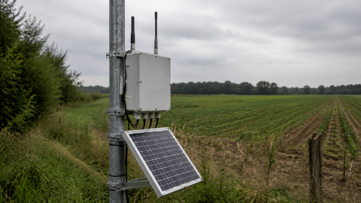
Outdoor LoRaWAN gateway with antennas and solar power panel mounted on a field pole

Solar Power for Off-Grid Telecom Sites

Keep small cells, wireless ISP relays, industrial cellular gateways, and LoRaWAN aggregation points online with an off-grid power platform sized from 24-hour consumption, worst-month solar input, battery autonomy, and the site's voltage, wind, shading, and lightning constraints.

Quick answer

Off-grid telecom is a continuous-load problem: a 10 W radio consumes 240 Wh every day before conversion losses and autonomy margin are added. LinkSolar supplies the power layer - solar array, LiFePO4 battery bank, MPPT controller, IP65 enclosure, protected outputs, monitoring, and mounting - for small cells, relays, gateways, and site-support loads. Kilowatt-scale macro towers are outside this platform family.

Who this solution is for

  • Wireless ISPs and private network operators

    Teams placing small cells and backhaul relays on ridges, silos, masts, and other locations beyond a reliable grid connection.

  • Rural connectivity programmes

    Public and private programmes extending communications coverage where a grid drop is slower or more expensive than a local solar power platform.

  • Industrial and mining operators

    Operators running private LTE, mesh backhaul, or remote communications infrastructure across large and difficult-to-access sites.

  • IoT network operators

    Teams powering LoRaWAN, NB-IoT, and industrial cellular gateways that aggregate many sleeping nodes but must remain online continuously.

Technical considerations

Comparison of solar panel and battery sizes for several classes of continuously operating industrial cellular gateway.

Continuous load

Size from 24-hour energy, not the radio nameplate

A telecom radio holds an association and keeps its backhaul online, so consumption is close to flat around the clock. A 10 W continuous load uses 240 Wh per day; at three worst-month peak-sun-hours and 25% system losses, it already requires roughly a 100 W array before any battery-autonomy margin is added.

The battery must carry the complete night every night and then cover the approved number of low-input days. Availability targets therefore drive both the stored-energy reserve and the recovery capacity of the array.

Build the budget from measured or datasheet watts for the radio, backhaul, router, controller, enclosure heater or fan, monitoring electronics, and conversion stages. Document the assumed connection state instead of hiding it inside a generic safety factor.

Review the 4G LTE gateway sizing guide

Electrical architecture

Confirm bank voltage and protected outputs before hardware selection

Many telecom radios expect 24 V or 48 V input. Starting with a 12 V battery and adding a boost converter introduces another conversion stage and another unattended failure point. Confirm the radio's input range, peak current, allowable voltage drop, and connector before fixing the bank voltage.

Use separate fused rails for the radio and site-support loads so a heater, fan, camera, or auxiliary device cannot pull down the communications link. Match the controller, battery-management system, cable gauge, protection devices, and low-voltage disconnect to both average energy and peak current.

Specify RS485, Modbus, or an equivalent remote status path at order time. Battery state of charge and charge current should become operational metrics rather than information discovered during a truck-roll.

Industrial cellular gateways powered by solar arrays across several representative remote deployment settings.

Field uptime

Engineer the site around shading, wind, moisture, and lightning

Telecom sites are selected for line of sight rather than solar aspect. Check the winter sun path, mast shadow, nearby structures, and vegetation, and be prepared to place the array away from the radio mast instead of accepting recurring partial shade.

Use a structure rated for the real mast or ridge wind exposure. Lightning and surge protection require site engineering on both DC and antenna paths; grounding, conductor routing, and protective-device coordination are not optional details on an exposed communications site.

An IP65 enclosure still needs moisture management. Sealed cabinets breathe through daily temperature cycles, so use suitable cable entries, drip loops, controlled ventilation, and an IP-rated breathable vent where the environmental design permits it.

Read the cold-climate battery field notes

Procurement and QA

Coordinate the power bill of materials before the rollout

LinkSolar acts as a sourcing and factory-side QA partner rather than claiming to manufacture every component. A telecom power platform may span panel, battery-pack, enclosure, controller, and mounting suppliers; the goal is one reviewed electrical and mechanical specification, one coordinated QC record, and one shipment plan.

Custom mini-panel samples are commonly quoted at 7-10 days, while integrated-system production and freight timing is confirmed after the load, bank voltage, mounting, enclosure, and quantity are fixed. Pilot quantities can start from an MOQ of 5 where the selected component suppliers support it.

The radio, backhaul equipment, antennas, and network configuration remain customer-supplied by default. This keeps the power platform vendor-neutral and forces the final design to use the actual equipment list instead of a generic telecom label.

Component layout for an off-grid industrial cellular gateway power system with solar array, battery, controller, protected output, and gateway.

Reference architecture

A resilient off-grid telecom power architecture

A typical platform combines a 200-800 W monocrystalline array, an MPPT controller, a 12 V or 24 V LiFePO4 battery bank within a 100-400 Ah planning range, an IP65 power enclosure, and protected outputs to the radio and support equipment. The final voltage and capacity follow the actual load schedule and availability target.

The battery carries the full night and the agreed low-input reserve; the array must both support the daytime load and recover that reserve. Separate rails and correctly coordinated surge protection prevent an auxiliary load or transient from taking down the communications link.

Remote battery status closes the operational loop. A slow decline can become a maintenance ticket before it becomes an outage, which is particularly valuable where access is seasonal or every truck-roll is expensive.

Review the remote solar power platform

Why telecom sizing is different

Duty cycle changes which assumption controls the array and battery. Telecom relays and gateways cannot claim the sleep savings available to many sensor nodes.

Why telecom sizing is different
Site typeDuty cycleWhat governs the sizing
Hydrology or weather node

Sleeps between samples; the radio may wake only for scheduled uplinks.

Worst-month sun and firmware duty cycle are the main sizing levers.

Fire detection camera

Often continuous by day and lower at night unless thermal sensing or other always-on loads are fitted.

Autonomy through a multi-day smoke or poor-weather event.

Telecom relay or gateway

Continuous, 24 hours per day.

Night-time draw sets the battery; the availability target sets the margin.

Use actual device datasheets and measured connection states. A nominal wattage without hours per day and conversion losses is not a complete energy budget.

Reference telecom power architecture

These are quotation and design-review ranges, not a substitute for a device-level load calculation, site solar study, and structural assessment.

Reference telecom power architecture
BlockTypical planning specificationWhy it matters on a telecom site
Solar array

200-800 W monocrystalline planning range.

The continuous load plus autonomy recovery normally places telecom above sensor-node panel sizes.

Battery bank

12 V or 24 V LiFePO4, commonly evaluated within a 100-400 Ah planning range.

It must carry the full night every night and then the approved low-input reserve.

Charge controller

MPPT controller matched to array voltage, battery chemistry, and charge current.

Diffuse-light recovery matters because poor-input days create the energy deficit.

Power enclosure

IP65 powder-coated metal cabinet with suitable sealed entries and controlled ventilation.

Protects the power electronics while managing condensation and daily temperature swing.

Protected outputs

Separate fused DC rails, with 24 V or other required output voltage confirmed from the radio datasheet.

Prevents a support load or transient from resetting the communications equipment.

Remote monitoring

Optional RS485, Modbus, or equivalent battery and controller status.

Turns a declining state of charge into a maintenance alert before it becomes a network outage.

Final array, battery, structure, and protection choices may fall outside these ranges when the measured load, climate, availability target, or site exposure requires it.

Recommended products and kits

  • Rendered side view of pole mount with framed panel tilted on round pole.
    Low-power gateways

    Adjustable pole mount for low-power gateway sites

    A mounting option for 30-60 W panels used on lower-power gateways, telemetry nodes, or secondary site-support loads. It is not sized for a 200-800 W small-cell or relay array; larger telecom sites require a project-specific structure and wind-load review.

    View the adjustable pole mount

Reference configurations

Typical configurations for planning reference; final sizing depends on site and load data.

Reference configurations
Scenario Reference solutionPanel and constructionExpected outcome
Industrial cellular or LoRaWAN gateway

A continuously connected gateway aggregating remote devices, with no high-power radio amplifier or large auxiliary load. A 10 W continuous example uses 240 Wh per day before system losses.

Begin above the roughly 100 W clear-sky calculation and evaluate the lower portion of the 200-800 W array and 100-400 Ah battery planning ranges after autonomy, worst-month sun, temperature, and conversion losses are applied.A planning reference for gateway sites. Final sizing depends on modem connection state, gateway processing load, radio transmit behaviour, climate, and availability target.
Wireless ISP relay with 24 V radio

An always-on point-to-point or point-to-multipoint relay with a 24 V radio, router or switch, and remote battery status.

Normally evaluated within the middle of the 200-800 W array and 100-400 Ah battery planning ranges, using a native 24 V architecture where compatible, MPPT charging, separate fused outputs, surge protection, and a wind-rated structure.Avoids an unnecessary 12 V boost stage and makes radio input, cable loss, autonomy, and remote maintenance visibility explicit in the approved specification.
Small cell with site-support loads

A continuously operating small cell or higher-power relay paired with routing, monitoring, and possible enclosure heating or ventilation loads.

Evaluate toward the upper part of the 200-800 W and 100-400 Ah planning ranges, or beyond them when the measured load, poor winter solar input, long autonomy, or thermal controls require it. Confirm native bank voltage, peak current, cabinet heat, and mounting loads.A custom engineered platform rather than a universal kit. Kilowatt-scale macro tower power and generator-hybrid systems remain outside this application scope.

Frequently asked questions

How much solar power does an off-grid telecom site need?

Work from 24-hour watt-hours, not average watts. A 10 W continuous load consumes 240 Wh per day, which at three worst-month peak-sun-hours and typical system losses implies roughly a 100 W array before autonomy margin. Small cells, relays, and gateway sites commonly require evaluation within a 200-800 W array and 100-400 Ah battery planning range, driven mainly by the measured load and availability target.

Why cannot I size a telecom site like a sensor station?

The duty cycle is the opposite. A sensor node may sleep between samples, so firmware choices dominate its energy budget. A telecom radio holds an association continuously, so there is no sleep saving to claim and the battery must carry the full load every night.

Should the battery bank be 12 V or 24 V?

Follow the radio input range and the overall system design. Many telecom radios expect 24 V or 48 V input, and running a 12 V bank through a boost converter adds a conversion stage and another possible failure point. A higher bank voltage can also reduce current and cable loss, but every controller, protection device, and load must be compatible.

Do you supply power for macro towers?

No. This platform family covers small cells, relays, gateways, and site-support loads. Kilowatt-scale macro tower power with generator hybridisation and multi-string arrays is a different engineering problem and supply chain.

How do I monitor battery health on an unattended site?

Specify remote battery telemetry at order time. RS485, Modbus, or an equivalent status path can report state of charge, charge current, voltage, and alarms so a slow decline becomes a maintenance ticket instead of an outage.

Plan the power layer for your off-grid telecom site

Send the radio and backhaul datasheets, average and peak watts, input-voltage range, required availability, site region, shading and wind conditions, enclosure requirements, and rollout quantity. LinkSolar will review the load schedule, voltage architecture, autonomy target, mounting, sample route, and delivery timeline, then respond to the RFQ within one business day.