Orderly failure
Quick answer
Who this solution is for
-
Water and wastewater utilities
Teams operating reservoir, pump-station, level, pressure, and network telemetry points beyond practical grid service.
-
Irrigation districts and scheme operators
Operators running gate, flow, pressure, and level outstations across distributed water infrastructure.
-
Pipeline and energy operators
Teams monitoring cathodic protection, wellhead or pipeline variables, and remote valve-station status where site classification must be confirmed.
-
SCADA and automation integrators
Integrators that own the RTU, PLC, instruments, communications, and control-system design and need a compatible remote power layer.
Technical considerations
Load accounting
Build the standing load from every powered loop and conversion stage

Telemetry and interfaces
Treat communications states and protocol integration as separate design questions

Field reliability
Design the enclosure, distribution, and surge paths as one system
Scope and compliance
Verify the exact document and certification set before procurement

Representative topology
A reference architecture with protected loads and observable power health
What to measure in a remote outstation load schedule
| Load | Measurement focus | Design consequence |
|---|---|---|
| RTU or small PLC | ||
| Powered process instruments | ||
| Telemetry radio or gateway | ||
| Actuator or valve interface | ||
| Cathodic-protection monitoring | ||
| Local HMI, display, or indicator |
Reference SCADA outstation power architecture
| Block | Selection basis | OT-specific check |
|---|---|---|
| Solar module | ||
| Battery | ||
| Charge and load controller | ||
| Protected DC distribution | ||
| Enclosure and field interfaces | ||
| Power-health monitoring |
Recommended products and kits
-
![2.1W 18V long rectangular mini solar panel with textured black ETFE front]() Measured low-duty endpoints
Measured low-duty endpoints2.1 W, 18 V ETFE panel for a measured low-duty endpoint
View the 2.1 W, 18 V ETFE panel -
![Side profile of aluminum pole mount with two hose clamps on a round pole.]() Compatible framed 5-50 W modules
Compatible framed 5-50 W modulesAdjustable pole mount for compatible framed 5-50 W modules
View the adjustable pole mount


Reference configurations
Typical configurations for planning reference; final sizing depends on site and load data.
| Scenario | Reference solution | Panel and construction | Expected outcome |
|---|---|---|---|
| Water level, pressure, or pump-status outstation | Measure RTU, I/O, loop supply, modem states, local indicators, and actuation over a representative cycle. Size the protected distribution, battery, controller, and array for worst-month conditions, defined autonomy, orderly undervoltage behaviour, and access constraints. | A representative utility outstation class, not a delivered project. The utility and integrator retain control-system, process-safety, communications, and site-acceptance responsibility. | |
| Pipeline or cathodic-protection monitoring point | Confirm measurement duty, radio coverage and retries, antenna and surge paths, cable lengths, corrosion exposure, battery temperature, service interval, and site classification before selecting any standard panel, enclosure, or mount. | A representative remote-monitoring class only. If the location is classified, use a separately engineered and certified hazardous-area supply path rather than this standard configuration. | |
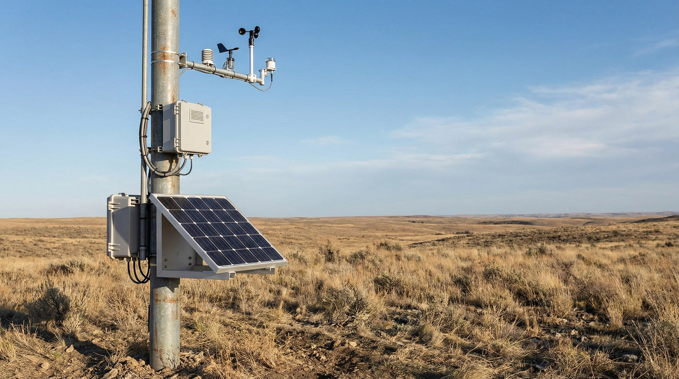
| Weather, environmental, or utility telemetry station | Use the measured sensor warm-up and sampling schedule, telemetry state log, heater controls, minimum temperature, seasonal shading, soiling, and recovery target. Include cabinet thermal and condensation review plus power-health signals appropriate to the service plan. | A representative telemetry architecture that demonstrates the power interfaces without implying a delivered LinkSolar installation or verified performance at a named site. |
