Des solutions solaires sur mesure pour propulser vos projets.

Alimentation de capteurs IoT, caméras de surveillance et stations météo dans plus de 20 pays.

Du prototype à la production en série — un seul fournisseur, un seul interlocuteur.

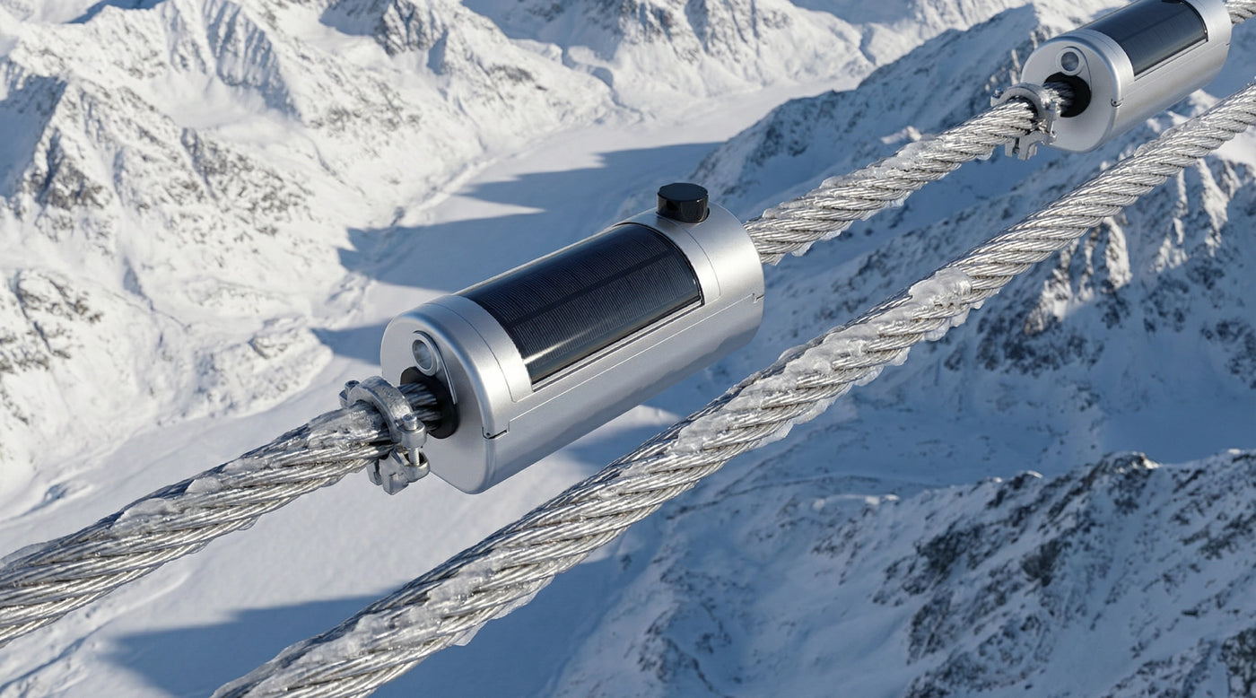
Solar sensors on icy transmission lines in a snowy mountain range.

Transmission Line Icing Monitoring System with Video Surveillance

A self-powered overhead-line monitoring node that combines visual evidence, conductor-temperature context, local storage, remote communications, and project-defined icing alerts for hard-to-access utility corridors.

Quick answer

The LS-9V6GB11110 is a reference icing-monitoring node for overhead transmission lines rated 35 kV and above. It combines a camera and selected line-condition inputs with line-energy induction, solar assistance, internal storage, and remote communications. The exact icing assessment method, camera configuration, sensing channels, power balance, image policy, alert logic, platform integration, and cold-weather limits must be confirmed for the supplied project configuration.

Who this solution is for

  • Utility operations teams

    Operators that need remote visual evidence and condition trends before deciding whether to patrol, dispatch, reroute, or escalate an icing event.

  • Transmission asset engineers

    Engineers responsible for identifying high-risk spans, reviewing icing progression, and defining monitoring and mitigation criteria.

  • Grid monitoring integrators

    Integrators designing cameras, sensing interfaces, 4G or other backhaul, storage, platform fields, alarms, history, and cybersecurity.

  • Pilot and rollout programs

    Programs comparing a known icing corridor with a normal span before standardizing hardware, image cadence, and alarm rules.

Technical considerations

LS-9V6GB11110 cylindrical self-powered overhead-line monitoring node with integrated solar surface.

Monitoring role

Combine visual evidence with line-condition context

The reference node supports video surveillance, icing assessment, and conductor-temperature monitoring so operators can review visible site evidence alongside condition data. This can help distinguish a developing icing event from a weather-only inference when the corridor is difficult to access.

Confirm the exact camera, lens, illumination, heater or anti-fog measures, image resolution, field of view, sensing channels, icing algorithm or assessment output, validation basis, and environmental limitations for the supplied model. A Page-level description is not a substitute for an approved measurement specification.

LINKSOLAR Power Line Monitoring Ecosystem LS-9V6GB11110

Energy continuity

Size induction, solar assistance, and storage for the worst operating state

The legacy reference combines line-energy induction, solar assistance, and an internal battery. The energy budget must cover sensing, processing, standby, scheduled status, image or video capture, local storage, 4G sessions, retransmissions, event uploads, and any cold-weather accessories.

Low temperature reduces usable battery energy and can limit charging. Weak line-current periods, poor winter solar input, snow or ice on exposed surfaces, and repeated image uploads may occur together, so final autonomy and recovery behaviour require worst-case corridor data rather than a nominal battery rating alone.

Representative overhead transmission corridor with solar-assisted line monitoring devices installed at remote spans.

Best-fit scenarios

Prioritize spans where visual confirmation changes the decision

Strong candidates include high-latitude or alpine corridors, mountain passes, river or canyon crossings, long spans, and lines with repeated icing history or costly patrol access. Site selection should consider wind, elevation, orientation, conductor and ground-wire geometry, communications coverage, maintenance access, and the operational value of visual confirmation.

A pilot should include a known or suspected high-risk span and a representative comparison span. That pairing helps the team tune image cadence and alerts while distinguishing site conditions from camera, radio, power, or platform behaviour.

Remote icing-monitoring camera view showing a snowy transmission corridor with line temperature, current, battery, solar, humidity, and 4G status overlays.

Integration and governance

Define how images, data, and alarms enter the utility workflow

Before deployment, define the normal image or video schedule, event triggers, evidence attached to an alarm, local retention, upload priority, bandwidth limits, dashboard fields, time synchronization, device-health status, user roles, and the action expected from each alarm level.

LinkSolar can review the node configuration, power assumptions, mounting information, and project interface. The utility or integrator remains responsible for communications coverage, cybersecurity, data governance, platform integration, alarm validation, live-line or outage procedures, structural review, and operational dispatch decisions.

Representative topology

Reference architecture for remote icing evidence and alerts

Line-energy induction and the solar input feed power management and internal storage. The node supplies the camera, conductor-temperature channel, selected condition inputs, processing, and local storage. Scheduled status and event evidence are transmitted through 4G or another project backhaul to a monitoring platform for visualization, history, and alarm handling.

The exact sensor interfaces, icing analysis, image and video retention, backhaul, cloud or on-premises platform, protocol, cybersecurity, and alarm workflow are project-specific. Confirm which components and software are included in the quotation rather than assuming this reference flow describes one fixed package.

System and environmental reference

These values come from the current legacy Page and require confirmation against the exact supplied model, drawing, interfaces, software scope, and approved datasheet.

System and environmental reference
ItemReference value
Model

LS-9V6GB11110.

Application

Overhead transmission lines rated 35 kV and above; confirm conductor, mounting, clearance, and utility procedures.

Power method

AC induction or line-energy harvesting with solar assistance and an internal battery; final input contribution depends on the selected configuration and site.

Battery

Listed 9.6 V, 14 Ah high-temperature lithium reference. Confirm chemistry, protection, low-temperature charging, usable capacity, transport documents, and replacement plan.

Communications

4G remote-monitoring reference with project-specific backhaul options. Confirm bands, carrier, SIM and data ownership, antenna, coverage, cybersecurity, and retry behaviour.

Core functions

Visual icing monitoring, video surveillance, conductor-temperature monitoring, and real-time platform alerts are listed. Confirm exact sensing channels, analysis output, evidence type, and software scope.

Local storage

Listed at 128 GB or greater. Confirm storage medium, usable capacity, recording mode, overwrite policy, export, encryption, and retention.

Ingress and temperature

IP66 and -40 deg C to +85 deg C environmental references. Confirm final assembly, camera, battery, connectors, sensors, and optional cold-weather components.

The exact camera, icing-assessment method, interfaces, environmental limits, and included platform functions must be stated in the approved project specification.

Pilot definition checklist

Pilot definition checklist
DecisionWhat to define
Pilot sites

Select a known or suspected high-risk corridor and a representative comparison span; document weather, history, access, conductor geometry, line current, solar exposure, and coverage.

Visual evidence

Define image or video resolution, field of view, day and night behaviour, scheduled cadence, event capture, local retention, upload priority, and operator access.

Alarm policy

Define sensing inputs, icing assessment output, trend and duration rules, alarm levels, evidence attached, acknowledgement, escalation, and dispatch criteria.

Energy and communications

Measure worst-case sensing, processing, storage, 4G, upload, retry, heater or illumination, and standby states against line-energy, solar, and battery availability.

Platform integration

Confirm protocol, fields, timestamps, device health, image links, history, roles, cybersecurity, data ownership, retention, acceptance tests, and support boundaries.

Run the pilot through representative winter conditions before freezing the rollout configuration and alarm policy.

Reference configurations

Typical configurations for planning reference; final sizing depends on site and load data.

Reference configurations
Scenario Reference solutionPanel and constructionExpected outcome
Known high-risk icing corridor pilot

Deploy the reviewed node configuration at a span with documented icing exposure or difficult patrol access, and collect scheduled images, condition data, device-health status, and event evidence through representative winter conditions.

Confirm line-current profile, winter solar input, camera view, cold-weather accessories, conductor and mounting interface, 4G coverage, local storage, installation method, and maintenance access.A corridor-specific evidence baseline and validated power, communications, and alarm workflow; not a guaranteed icing threshold for other spans.
Representative comparison span

Use a matching or controlled comparison node on a normal corridor so operators can compare image quality, sensor context, communications, and false-positive behaviour across different site conditions.

Keep camera settings, reporting cadence, timestamps, platform fields, and alarm evaluation consistent enough for a useful comparison.A comparison dataset for tuning evidence requirements and identifying which differences are caused by the corridor rather than the monitoring chain.
Standardized rollout after winter validation

Freeze the approved model suffix, camera and sensor configuration, power options, firmware, retention, upload behaviour, gateway or backhaul, platform schema, alarms, labels, and acceptance tests after the pilot.

Plan device inventory, data costs, storage, spares, battery and optical maintenance, cleaning, inspection, commissioning records, and support ownership.A repeatable deployment class with documented acceptance and evidence policies; each span still requires installation and communications review.

Frequently asked questions

Is this a complete icing-monitoring node or only a camera?

The reference is a self-powered monitoring node that can combine video, icing assessment, conductor-temperature context, local storage, remote communications, and platform alerts. The exact camera, sensors, analysis, power options, backhaul, gateway, and software included must be confirmed in the project quotation and specification.

How does the node remain online during storms and long nights?

The current design reference combines line-energy induction, solar assistance, and an internal battery. Actual uptime depends on line current, winter solar input, temperature, battery condition, sensing and processing load, image capture, 4G sessions, retransmissions, heaters or illumination, and maintenance. Size and test the worst operating state rather than relying on battery capacity alone.

What types of icing alerts can be configured?

Projects may use visual assessment, selected sensor thresholds, trend changes, duration rules, and evidence such as images or clips. The exact icing algorithm, input channels, alarm output, confidence or severity fields, and evidence policy depend on the supplied system and utility requirements. Validate every alarm class during the pilot before connecting it to dispatch.

Can the node work with an existing power-line monitoring platform?

Yes, through project-level integration. Define protocols, fields, timestamps, device-health status, image or video links, retention, user roles, alarm rules, cybersecurity, data ownership, and acceptance tests. Confirm whether LinkSolar, the platform vendor, or the utility integrator owns each interface and support responsibility.

Should the project start with a pilot or a full rollout?

Start with a pilot that includes a high-risk corridor and a representative comparison span. Validate winter power balance, image quality, communications, evidence usefulness, alarm behaviour, platform integration, and maintenance access before freezing the hardware, firmware, retention, and alarm policy for scale.

Define an icing-monitoring pilot around your corridor and evidence needs

Send the target voltage class, conductor and span information, icing history, line-current profile, winter solar and temperature conditions, camera and sensing requirements, required evidence, alert and dispatch rules, 4G or platform constraints, local retention, installation method, pilot quantity, and documentation requirements. LinkSolar will review a project configuration and pilot scope for quotation.