Zonne-oplossingen op maat die uw projecten vooruit helpen.

Voeding voor IoT-sensoren, beveiligingscamera's en weerstations in 20+ landen.

Van prototype tot productie — één leverancier, één contactpersoon.

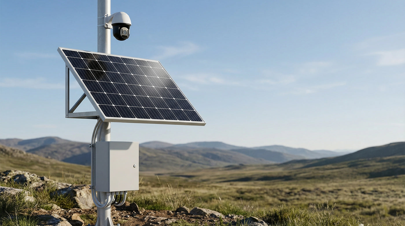
Remote solar power system powering a pole-mounted security camera with a monocrystalline solar panel, triangle bracket, and waterproof battery box.

Solar Power for Forest Fire Detection Cameras

Keep optical, thermal, PTZ, edge-processing, and telemetry equipment online through smoke-reduced solar input with a power platform engineered for continuous loads, five-day-or-longer autonomy, exposed ridge sites, and difficult emergency access.

Quick answer

A forest-fire detection camera normally consumes far more energy than a duty-cycled remote sensor because the camera, processor, and often the radio run continuously. A 100-400 W solar array with a 100-200 Ah LiFePO4 battery is a practical starting range for many tower and ridge installations, but the final system must be calculated from the actual device datasheets, smoke-attenuated irradiance, required autonomy, temperature range, PTZ surge current, and the site's wind and lightning exposure.

Who this solution is for

  • Fire detection system integrators

    Teams deploying optical, thermal, or AI-assisted camera networks across ridgelines, lookout towers, communication masts, and remote forest corridors.

  • Utilities and grid operators

    Operators adding wildfire detection and visual verification along transmission corridors as part of resilience and risk-mitigation programmes.

  • Forestry agencies and land managers

    Public and private land managers building early-detection networks against a fixed fire-season readiness deadline.

  • Satellite-IoT and telemetry providers

    Connectivity providers whose end customers need the tower-side panel, battery, controller, enclosure, and mounting hardware delivered as one coordinated power specification.

Technical considerations

Primary design constraint

Design for the smoke event, not the clear-sky average

The event a fire camera exists to detect can also reduce its energy supply. Dense smoke behaves like a persistent regional overcast, while ash and dust add a longer-lasting loss until the module is cleaned or washed by rain. A platform sized only from seasonal peak-sun-hours can therefore fail during the most important week of the year.

Start with the required no-charge autonomy and work back to the array size. Ordinary remote monitoring may tolerate one to three days without meaningful charge; a critical fire camera should normally be evaluated for at least five days, with a longer reserve where smoke, winter weather, or emergency road closures can persist.

The sizing model should include smoke and soiling derates, charge-controller and cable losses, battery temperature limits, ageing margin, and the minimum acceptable state of charge at the end of the design event. These assumptions should be documented instead of hidden inside a generic safety factor.

Two solar-powered remote camera and weather-monitoring poles in an arid landscape, illustrating continuous and peak loads from cameras, communications, and sensors.

Load profile

Build the budget around continuous and peak loads

An optical camera may run continuously during daylight, while a thermal sensor removes the night-time saving entirely. Edge inference adds a steady processing load, and an always-on cellular link can consume more than 25-30 Wh/day before camera demand is counted.

PTZ movement, heaters, defoggers, and radio transmit bursts introduce peak-current requirements that daily watt-hours alone will not reveal. The battery, wiring, fuses, controller outputs, and low-voltage disconnect must all support those bursts without resetting the radio or edge computer.

Use separate fused rails for the camera and communications equipment, or for other loads with very different surge profiles. The shared battery bank can remain one coordinated system while each critical device receives appropriate protection and cable sizing.

Review the cellular camera power guide

Open weatherproof enclosure containing a battery bank, charge controller, fused outputs, and organised field wiring on a solar-powered remote site.

Field reliability

Engineer the enclosure, protection, and wiring for exposed sites

Ridge and lookout sites combine high wind, lightning exposure, large daily temperature swings, vibration, ash, and difficult access. Use a wind-rated mounting structure, a ventilated IP65 or better enclosure appropriate to the site, drip loops and sealed cable entries, and surge protection on exposed camera and telemetry lines.

Leave an air gap behind the solar module rather than fixing it flush to a hot surface. Short DC runs and correctly sized conductors reduce voltage drop; secure terminations and strain relief reduce vibration failures. Low-voltage disconnect or graceful shutdown logic helps protect equipment and stored data during an extended low-input event.

Battery chemistry and charging controls must reflect both fire-season heat and the site's coldest charging conditions. LiFePO4 offers useful cycle life and usable capacity, but low-temperature charging limits and enclosure thermal design still require explicit review.

Read the cold-climate battery field notes

Procurement and QA

Coordinate the power bill of materials before fire season

LinkSolar acts as a sourcing and factory-side QA partner rather than claiming to manufacture every component. A fire-camera power platform may span panel, battery-pack, enclosure, controller, and bracket suppliers; the goal is one reviewed electrical and mechanical specification, one coordinated pre-shipment QC record, and one shipment plan.

Custom mini-panel samples are commonly quoted at 7-10 days, while integrated-system timing is confirmed after the load, mounting, enclosure, and quantity are fixed. A representative ocean-freight programme can take roughly 8-13 weeks from sample approval to installation, so the ordering date should be planned back from the required seasonal readiness date.

Pilot quantities can start from an MOQ of 5 where the selected component suppliers support it. Cameras, radios, and detection software remain customer-supplied by default, allowing the power platform to remain camera-agnostic and sized from the actual equipment list. Final MOQ and lead time are confirmed in the project quote.

Solar-powered fire detection camera station with a large array, weatherproof equipment enclosure, antenna, and secondary monitoring node on a forested hillside.

Reference architecture

A resilient five-block fire-camera power architecture

A typical platform combines a monocrystalline solar array, an MPPT controller, a 12 V LiFePO4 battery bank, a weatherproof power enclosure, and protected outputs to the camera, processor, and communications equipment. The array is sized against smoke-reduced input; the battery is sized against the required no-charge autonomy and the highest continuous load profile.

Separate fused output rails keep PTZ movement, heaters, or other burst loads from pulling down the radio or edge computer. The controller, battery-management system, cable gauge, connectors, and low-voltage disconnect must be compatible with both average daily energy and peak current.

A 100-400 W array and 100-200 Ah battery are planning ranges, not a universal kit specification. Optical-only, PTZ, thermal, and edge-AI stations can occupy very different points inside or beyond that range, so the design is finalised only after the camera, radio, processor, heater, site climate, and autonomy requirement are known.

Review bracket selection for pole-mounted cameras

What a fire detection station actually draws

Use the actual equipment datasheets and operating schedule. The entries below identify the load behaviours that most often change the final power specification.

What a fire detection station actually draws
LoadDraw patternEffect on the power budget
Optical camera

Continuous during the configured monitoring period.

Often dominates the daytime budget and offers little duty-cycle saving.

Pan-tilt-zoom mechanism

Short peak load whenever the head slews or follows a patrol schedule.

Peak current, wiring, and output-rail separation matter in addition to daily watt-hours.

Thermal sensor

Continuous day and night when fitted.

Removes the night-time saving and can move the design toward or beyond the upper planning range.

Edge processing unit

Continuous base load with higher demand during inference.

Reduces uplink traffic but adds local energy use and enclosure heat.

Telemetry radio

Continuous or duty-cycled according to the connection design.

An always-on cellular link can exceed 25-30 Wh/day before camera demand is counted.

Heater or defogger

Seasonal or condition-triggered load.

Frequently omitted from early budgets and added later, forcing an array or battery revision.

Record average watts, peak watts, hours per day, connection state, and seasonal operating rules for every device before selecting the array and battery.

Reference power architecture

These are planning specifications for quotation and design review, not a substitute for a device-level energy calculation and site structural assessment.

Reference power architecture
BlockTypical planning specificationWhy it matters on a fire-camera site
Solar array

100-400 W monocrystalline planning range.

Must be sized against smoke-reduced input, soiling, temperature, and worst-season solar availability.

Battery bank

12 V LiFePO4, commonly 100-200 Ah within the planning range.

Autonomy, peak discharge, low-temperature charging, heat, ageing, and end-of-event state of charge all affect selection.

Charge controller

MPPT controller matched to array voltage, battery chemistry, and charge current.

Improves energy capture under changing and diffuse-light conditions while enforcing the correct charging profile.

Power enclosure

IP65 or better where appropriate, with sealed entries and controlled ventilation.

Protects batteries and controls while managing ridge-site condensation and temperature swing.

Protected outputs

Separate fused DC rails for camera/PTZ loads and radio/processor loads.

Reduces the risk that a motor or heater burst resets communications or corrupts the edge system.

Mounting structure

Pole, mast, or tower mount engineered for the actual module area and site wind exposure.

Ridgelines and lookout towers are highly exposed; grounding and lightning protection require site engineering.

The final platform may fall below, within, or above these ranges depending on continuous load, smoke derate, autonomy, heating, and climate.

Representative procurement timing

Use this sequence for early schedule planning, then confirm every duration against the approved specification, quantity, supplier capacity, freight route, and installation window.

Representative procurement timing
StageRepresentative duration
Specification confirmation and samples

Commonly 7-10 days for custom mini-panel samples; integrated platforms are confirmed at quote.

Production run

Approximately 2-4 weeks after sample and specification approval.

Ocean freight

Approximately 4-6 weeks, subject to origin, destination, route, and customs conditions.

Site installation window

Approximately 1-2 weeks, depending on tower access, permits, weather, and field-team availability.

Total from sample to installation

Roughly 8-13 weeks for representative ocean-freight planning; final timing is confirmed in the project schedule.

Air freight may shorten transit at a higher unit cost. Plan backward from the required fire-season readiness date rather than relying on an expedited final shipment.

Recommended products and kits

  • Side profile of aluminum pole mount with two hose clamps on a round pole.
    Supporting nodes

    Adjustable pole mount for smaller supporting nodes

    A mounting option for 5-50 W panels used on lower-power sensor, telemetry, or secondary visual-verification nodes in the same network. It is not sized for the 100-400 W main fire-camera array; the main tower structure requires a project-specific bracket and wind-load review.

    View the pole mount kit
  • Rendered side view of pole mount with framed panel tilted on round pole.
    Low-power gateways

    Adjustable pole mount for low-power gateway sites

    A mounting option for 30-60 W panels used on lower-power gateways, telemetry nodes, or secondary site-support loads. It is not sized for a 200-800 W small-cell or relay array; larger telecom sites require a project-specific structure and wind-load review.

    View the adjustable pole mount

Reference configurations

Typical configurations for planning reference; final sizing depends on site and load data.

Reference configurations
Scenario Reference solutionPanel and constructionExpected outcome
Fixed optical camera with cellular telemetry

A continuously operating optical camera with periodic or always-on cellular connectivity, without thermal imaging or a high-power on-tower inference computer.

Planning range: 100-400 W monocrystalline array, 12 V LiFePO4 battery within the 100-200 Ah range, MPPT controller, IP65 or better enclosure, separate fused camera and radio outputs, and a wind-rated mount.A baseline reference for fixed-camera sites. Final sizing depends on camera day/night mode, modem connection state, smoke derate, minimum temperature, and required autonomy.
PTZ camera with on-tower edge processing

A pan-tilt-zoom camera performing scheduled patrols, paired with an edge computer that analyses imagery locally and sends alerts or selected frames over the telemetry link.

Normally evaluated toward the upper portion of the 100-400 W and 100-200 Ah planning ranges, with MPPT charging, peak-current validation, separate fused rails, surge protection, and thermal management for the processor and battery enclosure.Local processing can reduce uplink traffic but raises the continuous site load. PTZ slew current and processor demand must be measured rather than estimated from camera nameplate power alone.
Optical and thermal day-and-night station

A dual-sensor station that combines daylight visual detection with continuous thermal monitoring through the night, often with a permanently connected radio and optional edge inference.

Treat the thermal channel as a continuous 24-hour load and verify whether the result remains inside the 100-400 W and 100-200 Ah planning ranges. Sites with longer autonomy, heaters, or large processors may require a larger custom platform.Removing the night-time saving materially increases daily energy and battery capacity. This configuration always requires a complete device-level load schedule and site solar study.

Frequently asked questions

How much solar power does a forest-fire detection camera need?

A 100-400 W array with a 100-200 Ah LiFePO4 battery is a practical starting range for many tower-mounted optical systems. Thermal imaging, edge processing, PTZ patrols, always-on radio links, heaters, longer autonomy, and poor solar conditions can move the requirement upward. Final sizing must use the actual equipment schedule and site data.

Why do fire cameras need more battery autonomy than ordinary remote sites?

Because the event they detect can reduce their charging input. Dense smoke may behave like multi-day regional overcast, while ash and dust remain on the module afterward. A critical fire-camera site should normally be evaluated for at least five days without meaningful charging, with the final target set by project risk and climate.

Does wildfire smoke reduce solar output?

Yes. Smoke scatters and absorbs incoming light, reducing the energy available to the array, and heavy conditions can persist for days. Ash and dust add a separate soiling loss until cleaning or rainfall restores the module surface. Both effects belong in the design derate and maintenance plan.

Can one solar system power the camera, processor, and radio?

Yes, and one coordinated battery bank is often the cleanest architecture. Use appropriately sized separate fused outputs so PTZ movement, heaters, or another burst load cannot brown out communications or the edge computer. Validate controller output limits, cable gauge, voltage drop, and peak current.

What is the lead time for a fire-camera power platform?

Custom mini-panel samples are commonly quoted at 7-10 days. A representative integrated-platform programme using ocean freight may take roughly 8-13 weeks from sample approval to installation. Final timing depends on the approved specification, quantity, suppliers, freight route, customs, and site access, and is confirmed in the quote.

Plan the power platform for your fire-detection network

Send the camera, thermal sensor, processor, and radio datasheets; tower count; site region; PTZ schedule; heater or defogger requirements; and target autonomy. LinkSolar will review the load profile, smoke and climate assumptions, enclosure and mounting requirements, sample route, and delivery schedule, then respond to the RFQ within one business day.