Specialanpassade solenergilösningar som driver dina projekt framåt.

Driver IoT-sensorer, säkerhetskameror och väderstationer i över 20 länder.

Från prototyp till produktion — en leverantör, en kontakt.

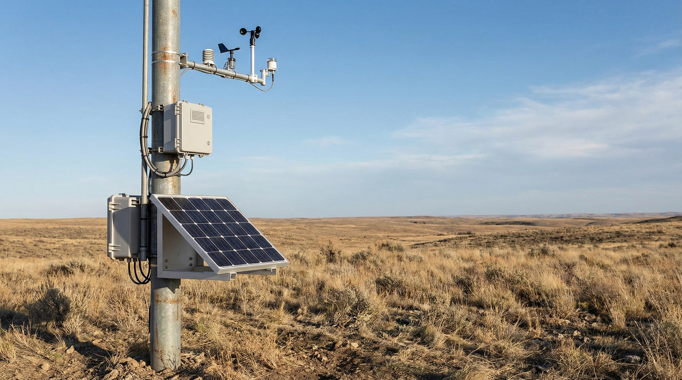
Remote solar power system supporting an environmental monitoring station with a solar panel, charge controller enclosure, and outdoor battery storage.

Solar Power for SCADA and Remote Telemetry Outstations

Power remote RTUs, small PLCs, process instruments, and telemetry links from a documented solar and battery platform. LinkSolar sizes the power layer from measured continuous loads, communications states, actuation peaks, worst-month solar input, temperature, required autonomy, and defined undervoltage and restart behaviour.

Quick answer

A SCADA outstation is not necessarily a large energy load, but it is a strict integration problem. The RTU, powered instrument loops, telemetry equipment, and any local display create a continuous baseline; actuators add peak-current events. The power design should define low-voltage behaviour, restart hysteresis, monitored battery signals, protected load branches, and documentation boundaries instead of relying on a generic panel-and-battery range.

Who this solution is for

  • Water and wastewater utilities

    Teams operating reservoir, pump-station, level, pressure, and network telemetry points beyond practical grid service.

  • Irrigation districts and scheme operators

    Operators running gate, flow, pressure, and level outstations across distributed water infrastructure.

  • Pipeline and energy operators

    Teams monitoring cathodic protection, wellhead or pipeline variables, and remote valve-station status where site classification must be confirmed.

  • SCADA and automation integrators

    Integrators that own the RTU, PLC, instruments, communications, and control-system design and need a compatible remote power layer.

Technical considerations

Orderly failure

Define undervoltage, shutdown, and restart behaviour as control states

A low-voltage disconnect can prevent an RTU or PLC from operating in an unstable brownout region, but it does not by itself guarantee an orderly application shutdown. Configuration retention, buffered-data handling, output state, and any shutdown input or hold-up requirement must be checked against the actual automation hardware.

Set the disconnect threshold from the load's minimum input voltage, battery chemistry, temperature, wiring drop, converter limits, and expected peak-current sag. Define reconnect voltage, delay, and hysteresis so the site does not repeatedly cycle as solar charge returns.

Bench-test low-energy behaviour with the final RTU firmware, I/O modules, radio, and power components. Record what happens to outputs, buffered values, communications, and local logic during shutdown and recovery.

Load accounting

Build the standing load from every powered loop and conversion stage

Start with measured input power for the RTU or PLC, I/O modules, isolators, signal conditioners, DC converters, powered instruments, local display, and telemetry equipment. A nominal 4-20 mA loop also has transmitter supply voltage, loop burden, isolation, and conversion losses that belong in the continuous baseline.

Measure normal, alarm, startup, transmit, retry, and actuator states over a representative operating cycle. Daily watt-hours determine energy, while simultaneous valve, radio, heater, or inrush events determine conductor, fuse, converter, and battery peak-current requirements.

Keep low-duty sensor endpoints separate from full outstations. A compact endpoint that wakes and reports periodically can use a much smaller power class than an RTU with continuous loops and an always-registered modem.

Representative SCADA gateway cabinet used to integrate DNP3 or Modbus monitoring data.

Telemetry and interfaces

Treat communications states and protocol integration as separate design questions

A radio or cellular gateway may draw differently while searching, registering, idling, transmitting, retrying, or operating in weak coverage. Log those states with the intended antenna, network, polling interval, payload, and fallback behaviour instead of using one catalogue current.

DNP3, Modbus, or another application protocol does not define the physical telemetry path or guarantee that battery data will reach the control room. Confirm the controller or BMS register map, gateway support, scaling, stale-data handling, alarm thresholds, and how maintenance events are routed.

Coordinate antenna placement, coaxial loss, surge protection, bonding, and separation from instrument wiring with the integrator. LinkSolar supplies the power layer; SCADA configuration, radio engineering, and OT cybersecurity assessment remain outside that scope.

Review SCADA integration considerations

Representative inspection of a remote monitoring power enclosure with battery, charge controller, telemetry modem, terminal blocks, and test equipment.

Field reliability

Design the enclosure, distribution, and surge paths as one system

Use separate protected branches where actuation, heaters, or radio peaks could disturb instrument loops or logic power. Select fuses, breakers, terminals, conductors, DC converters, and grounding from the real fault and surge environment, not only the average load.

An ingress rating does not solve condensation or internal temperature rise. Review cabinet volume, solar gain, battery and electronics heat, breathable vent selection, drainage, cable entry orientation, corrosion exposure, insect control, and the service method for the local climate.

Battery voltage, current, temperature, controller state, low-voltage events, and reset counters can make power health visible to operations. State-of-charge estimates are model-dependent, so alarm design should use the signals and accuracy available from the selected battery and controller.

Review battery selection for remote sites

Scope and compliance

Verify the exact document and certification set before procurement

For each supplied component, identify the exact model, drawing revision, electrical limits, environmental rating, battery transport documents, test or inspection record, and any market-specific conformity evidence required by the buyer. A general supplier or factory statement is not evidence for every assembled configuration.

Confirm site classification at the beginning. LinkSolar does not represent the standard power platform as an ATEX, IECEx, or other hazardous-area certified assembly. Classified sites require a specialist design, approved components, installation methods, and certification path.

The integrator remains responsible for RTU or PLC programming, control philosophy, fail-safe output states, communications, functional safety where applicable, cybersecurity, and acceptance of the complete operational system.

Representative off-grid solar power layout for an industrial cellular gateway and remote telemetry load.

Representative topology

A reference architecture with protected loads and observable power health

A representative outstation uses a solar module, chemistry-compatible charge controller, battery, surge and overcurrent protection, and regulated distribution to the RTU or PLC, instrument supply, telemetry gateway, and any actuator interface. Optional power-health signals return through a supported local interface to the automation system.

Choose the bank and distribution voltage from the actual device inputs, current, cable length, conversion efficiency, standard spares, and service practice. A correctly selected DC converter can be appropriate; its efficiency, standby draw, transient response, protection, and failure mode must be included rather than treating every extra conversion stage as automatically unacceptable.

Final module and battery capacity follow the measured 24-hour load, worst-month solar input, temperature, shading, soiling, autonomy requirement, permissible controlled load shedding, and recovery time after a low-sun event. The diagram and configurations are representative, not delivered-site evidence.

Review the remote solar power platform

What to measure in a remote outstation load schedule

Record voltage and current at the power-system input through normal, alarm, startup, communications, and actuation states. Catalogue values are useful for a first pass, but final sizing should use representative measurements and the intended firmware and network configuration.

What to measure in a remote outstation load schedule
LoadMeasurement focusDesign consequence
RTU or small PLC

Base CPU, I/O modules, scan state, communications ports, startup, and configuration-retention behaviour.

Creates a continuous logic baseline and defines the acceptable undervoltage and restart envelope.

Powered process instruments

Transmitter supply voltage and current, loop count, isolators, barriers, signal conditioners, and converter losses.

Each continuously powered loop adds to the standing load; intrinsically safe barriers require a separate classified-site review.

Telemetry radio or gateway

Search, register, idle, receive, transmit, retry, polling, weak-signal, and fallback states with the final antenna path.

Network behaviour may exceed the RTU load and can change after firmware, carrier, protocol, or coverage changes.

Actuator or valve interface

Inrush, pull-in, holding current, duration, frequency, simultaneous operations, and required fail-safe position.

Peak current, voltage sag, protected-branch separation, and control consequences can govern even when daily energy is modest.

Cathodic-protection monitoring

Measurement interface, sampling and logging schedule, radio states, isolation, surge path, and local environment.

The acquisition load may be low, but radio coverage, isolation, corrosion, and site classification can drive the system design.

Local HMI, display, or indicator

Backlight state, heater or cooling, sleep control, user-access schedule, and any alarm indication.

A convenience load can become a material continuous baseline if it remains illuminated or temperature-controlled.

Re-measure after changes to I/O count, transmitter type, modem firmware, carrier, antenna, polling interval, local display, or control sequence.

Reference SCADA outstation power architecture

These are selection and interface criteria, not fixed watt, amp-hour, voltage, or product ranges. The final design follows the locked load schedule and site requirements.

Reference SCADA outstation power architecture
BlockSelection basisOT-specific check
Solar module

Worst-month energy, controller input range, temperature, shading, soiling, recovery target, and mounting area.

Use the continuous loop and communications baseline plus controlled-load scenarios, not the RTU nameplate alone.

Battery

Chemistry, usable capacity at temperature, charge limits, peak current, cycle profile, autonomy, and service interval.

Set reserve from the operational consequence of lost visibility or control and the site's recovery and access constraints.

Charge and load controller

Array and battery voltage, charge profile, efficiency, self-consumption, load outputs, disconnect controls, and telemetry.

Document disconnect, reconnect, delay, and hysteresis against RTU input limits and the tested shutdown and restart sequence.

Protected DC distribution

Bank voltage, regulated rails, converters, fuses or breakers, terminals, cable drop, surge protection, bonding, and grounding.

Keep logic and instrument supplies stable during radio, actuator, heater, or other transient events.

Enclosure and field interfaces

Ingress, thermal rise, solar gain, condensation, venting, corrosion, glands, drainage, access, and site classification.

Coordinate power, signal, antenna, and earth paths; use a specialist certified design where the location is classified.

Power-health monitoring

Available battery and controller voltage, current, temperature, alarms, state estimates, event logs, and communications registers.

Define register mapping, scaling, stale-data detection, thresholds, alarm routing, and the maintenance response with the integrator.

Bench-test the complete outstation through startup, normal operation, communications loss, low-voltage shutdown, solar recovery, and restart before field rollout.

Recommended products and kits

  • 2.1W 18V long rectangular mini solar panel with textured black ETFE front
    Measured low-duty endpoints

    2.1 W, 18 V ETFE panel for a measured low-duty endpoint

    Consider this long-format OEM panel only for a dedicated sensor or telemetry endpoint whose complete measured energy budget fits the worst-month input and required reserve. Confirm the 18 V electrical interface, charge controller or regulator, battery chemistry, exposed-pad sealing, enclosure integration, temperature, shade, soiling, vibration, and cable termination. It is not a default panel for a continuously powered RTU, multiple 4-20 mA loops, an always-on gateway, or actuation.

    View the 2.1 W, 18 V ETFE panel
  • Side profile of aluminum pole mount with two hose clamps on a round pole.
    Compatible framed 5-50 W modules

    Adjustable pole mount for compatible framed 5-50 W modules

    Use this bracket only when the selected framed module, mounting-axis dimension, and pole diameter fit the product's stated range. The full installation still requires site-specific checks for wind, footing, clamp retention, corrosion, antenna clearance, cable support, access, tampering, and the inspection interval. It is not a universal structure for larger outstation arrays or a hazardous-area approval.

    View the adjustable pole mount

Reference configurations

Typical configurations for planning reference; final sizing depends on site and load data.

Reference configurations
Scenario Reference solutionPanel and constructionExpected outcome
Water level, pressure, or pump-status outstation

A remote RTU reads several powered instruments, logs events, and reports through cellular, licensed radio, or another telemetry path. A valve or pump interface, if present, is treated as a separate peak-current and fail-safe load.

Measure RTU, I/O, loop supply, modem states, local indicators, and actuation over a representative cycle. Size the protected distribution, battery, controller, and array for worst-month conditions, defined autonomy, orderly undervoltage behaviour, and access constraints.A representative utility outstation class, not a delivered project. The utility and integrator retain control-system, process-safety, communications, and site-acceptance responsibility.
Pipeline or cathodic-protection monitoring point

A low-duty acquisition unit measures cathodic-protection or process variables and reports periodically, while a continuously powered communications device may still determine the baseline.

Confirm measurement duty, radio coverage and retries, antenna and surge paths, cable lengths, corrosion exposure, battery temperature, service interval, and site classification before selecting any standard panel, enclosure, or mount.A representative remote-monitoring class only. If the location is classified, use a separately engineered and certified hazardous-area supply path rather than this standard configuration.
Weather, environmental, or utility telemetry station

A datalogger or small RTU powers a sensor suite, stores observations, and sends scheduled reports. Optional heaters, aspirators, cameras, or continuous cellular registration can move the station into a different load class.

Use the measured sensor warm-up and sampling schedule, telemetry state log, heater controls, minimum temperature, seasonal shading, soiling, and recovery target. Include cabinet thermal and condensation review plus power-health signals appropriate to the service plan.A representative telemetry architecture that demonstrates the power interfaces without implying a delivered LinkSolar installation or verified performance at a named site.

Frequently asked questions

How much solar power does a remote RTU need?

Calculate it from measured input watt-hours per day and peak current for the RTU or PLC, every powered instrument and conversion stage, telemetry states, local indicators, and actuation. Then apply worst-month solar input, temperature, shade, soiling, conversion losses, autonomy, controlled-load behaviour, and recovery time. A broad panel or battery range cannot replace that calculation.

Why does a SCADA site need more than a large battery?

Capacity reduces how often low energy occurs, but the system still needs defined behaviour when it does. Set disconnect and reconnect thresholds to avoid brownout and cycling, then test configuration retention, buffered data, output state, radio recovery, and any supported shutdown input. An LVD protects an electrical boundary; it does not automatically flush files or make application logic safe.

Should an outstation battery bank be 12 V or 24 V?

Choose from the RTU, instrument, radio, and actuator input requirements, current, cable length, standard spares, and conversion strategy. A higher distribution voltage can reduce current and cable loss, while a well-selected converter can provide a valid interface. Include converter efficiency, standby load, transient response, protection, and failure behaviour in the comparison.

Can the control system monitor the battery and solar controller?

Yes, when the selected battery, BMS, or controller exposes compatible data and the gateway is configured to carry it. Confirm registers, scaling, accuracy, update rate, stale-data handling, and alarm routing. Voltage, current, temperature, controller state, low-voltage events, and reset counters may be more actionable than a single state-of-charge estimate.

Is the standard power platform certified for hazardous areas?

No. Do not treat the standard platform as an ATEX, IECEx, or other hazardous-area certified assembly. Confirm area classification before specifying hardware. Classified sites require approved components, installation methods, documentation, and a specialist engineering and certification path for the complete assembly.

Plan the power layer for your remote outstations

Send the RTU or PLC and I/O datasheets, powered-loop count and supply details, measured current logs, telemetry device and operating states, antenna and coverage notes, actuator or heater schedule, bank-voltage preference, minimum temperature, site solar and shade information, autonomy target, enclosure constraints, site classification, rollout quantity, and required document set. LinkSolar will review the power architecture and component scope for a project quotation.