Specialanpassade solenergilösningar som driver dina projekt framåt.

Driver IoT-sensorer, säkerhetskameror och väderstationer i över 20 länder.

Från prototyp till produktion — en leverantör, en kontakt.

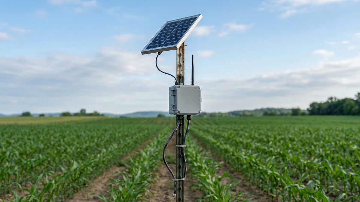
Precision agriculture IoT sensor node with solar panel on T-post in crop field

Solar Power for Agricultural Monitoring Networks

Power soil, micro-climate, irrigation, and field-monitoring nodes without extending wired power across every block. LinkSolar helps separate low-duty sensors from valve, cellular, camera, and heated loads, then specifies the panel, battery, controller, enclosure, and mounting layer from measured energy use, worst-month solar input, field conditions, and the service target.

Quick answer

Agricultural monitoring is a fleet-design problem as well as an energy problem. Small specification choices repeat across dozens or hundreds of nodes, while valve actuators, always-connected modems, cameras, and heaters can change the load class completely. Measure each operating state, size for the worst solar month and expected canopy, and set autonomy according to the consequence of a data or control gap instead of applying one oversized kit to the whole network.

Who this solution is for

  • Agricultural technology providers

    Teams integrating solar power into soil moisture, micro-climate, irrigation, telemetry, or crop-monitoring products.

  • Irrigation system integrators

    Integrators adding remote valve control, flow monitoring, and field communications across distributed irrigation schemes.

  • Large farms and cooperatives

    Operators deploying their own sensor fleets across fields, orchards, pasture, livestock areas, and water infrastructure.

  • Research and extension programmes

    Trial and monitoring teams that need unattended, repeatable data collection through a full growing season.

Technical considerations

Representative compact solar panel powering a generic agriculture sensor beside crop rows.

Per-node economics

Design the fleet by load class, not by one maximum case

A margin that is trivial on one station becomes a material cost when it is repeated across a large fleet. Start with measured watt-hours per day for each node type, including sleep, sensing, radio attach, transmission, actuation, illumination, and heating states.

Group nodes with similar energy and service consequences. Sleeping sensor nodes, valve controllers, continuously connected gateways, and camera or heated stations normally deserve separate power specifications rather than one platform sized around the largest load.

Use worst-month solar input, temperature-adjusted battery performance, conversion losses, crop shade, soiling, and the approved autonomy target to justify the margin in each class. This keeps reliability and fleet cost visible in the same decision.

Review agricultural IoT sensor sizing

Actuation loads

Confirm the valve type before sizing an irrigation controller

A latching solenoid uses a brief pulse to change state and no continuous power to hold position. A non-latching solenoid draws holding current for as long as the valve remains open. The same field controller can therefore move from a modest intermittent load to one of the largest loads in the network.

Record coil voltage, pull-in or pulse current, holding current where applicable, event duration, events per day, simultaneous-valve behaviour, controller losses, and the required fail-safe state. Check peak current and battery voltage sag as well as daily energy.

Keep actuation energy distinct from the radio and sensing budget so a valve event cannot reset communications. If valve type or duty cycle changes later, repeat the power calculation instead of assuming the original panel and battery still have adequate margin.

Representative agriculture sensor deployments across orchard, field, pasture, and irrigation settings.

Farm environment

Engineer for canopy growth, machinery, livestock, dust, spray, and corrosion

A clear installation point in spring may be shaded by a closed crop canopy in summer. Set the collection surface above the expected canopy or model the seasonal shade directly, and include dust or spray-film losses where field operations regularly soil the glass.

Place poles and enclosures outside machinery paths and make them visible from the cab. Where livestock can reach the installation, assess rubbing and impact loads as well as wind. Near livestock housing or manure storage, treat ammonia and persistent moisture as a corrosion exposure that affects fasteners, coatings, connectors, and glands.

Low field positions may be the correct sensing location but also the coldest and wettest point. Check battery temperature limits, drainage, condensation control, breathable vent selection, cable drip loops, and access for inspection or cleaning before standardizing the field kit.

Read the cold-climate battery notes

Lifecycle and OPEX

Specify serviceability and batch consistency as fleet requirements

A scheduled visit may be reasonable for a small trial, but repeated travel, access coordination, cleaning, battery replacement, and fault finding can dominate operating cost at fleet scale. Define the acceptable service interval and the consequence of a missed report or command before selecting the battery reserve and monitoring features.

Standardize connectors, polarity, fusing, glands, cable lengths, labels, mounting interfaces, and replaceable subassemblies within each load class. Remote battery voltage, charge state, reset count, or enclosure condition can help prioritize visits where failure has an operational consequence.

For production quantities, require reviewed drawings, electrical acceptance limits, ingress and strain-relief checks, and batch-level quality evidence appropriate to the application. Certification or compliance claims should be verified for the exact supplied component and market rather than assumed from a general supplier statement.

Review agriculture sensor sourcing considerations

Reference layout of weather-resistant solar power components for an agriculture sensor.

Reference architecture

A field-node architecture sized from measured states and service consequence

A typical field node connects the solar module to a chemistry-compatible charge controller and battery, then uses protected, regulated outputs for the sensor, radio, and any actuator. The enclosure, cable entries, connectors, mounting, and condensation strategy are part of the power system rather than accessories added after sizing.

Choose the controller from array and battery voltage, conversion efficiency across the real operating range, self-consumption, low-temperature charging requirements, load-control behaviour, telemetry needs, and cost. Do not select PWM or MPPT from a single panel-watt threshold.

The final panel and battery follow a measured 24-hour load schedule, modem state, actuator duty cycle, worst-month solar study, temperature, seasonal shade and soiling, required autonomy, and recovery time after a low-sun event. Use separate protected branches where actuation, IR illumination, or heating peaks could disturb sensing or communications.

Review the remote solar power platform

How small design choices scale across a field network

Evaluate each decision per node and across the planned fleet. The objective is not minimum first cost at any price; it is a justified balance of reliability, service effort, and repeatable hardware.

How small design choices scale across a field network
DecisionFleet effectReview action
Extra panel or battery margin

A small per-node increase becomes a material procurement and mounting cost across a large rollout.

Justify margin by load class using measured energy, worst-month solar, temperature, shade, soiling, autonomy, and recovery time.

Scheduled battery or cleaning visits

Travel, access, labour, and data interruption can dominate lifecycle cost when repeated across distant nodes.

Define the target service interval, cleaning access, replaceable parts, and remote health data before choosing the reserve.

Connector, gland, or cable defect

A modest defect rate becomes multiple dispersed field failures, often during the busiest season.

Standardize interfaces and acceptance checks for polarity, crimping, sealing, strain relief, and cable support.

Always-connected radio or modem

Idle, attach, retry, and poor-coverage behaviour can multiply both panel and battery requirements across the fleet.

Measure real network states and use batched communication only where latency and control requirements permit it.

Pilot each load class under representative temperature, coverage, crop, spray, and service conditions before committing to fleet quantities.

What to measure for common agriculture node types

Build the energy budget from time in each operating state. Use measured current and voltage where possible, then convert the complete schedule to watt-hours per day and peak-current requirements.

What to measure for common agriculture node types
Node typeMeasureDesign consequence
Soil moisture probe with batched radio

Sleep current, probe stabilization, sampling time, transmit current, retries, and reporting interval.

Often belongs in the smallest load class, but radio coverage and conversion self-consumption must still be verified.

Micro-climate station

Sensor warm-up, radiation or weather instruments, logger duty, radio schedule, and any fan or aspirator.

Additional instruments and sampling frequency can move the station out of the basic sleeping-sensor class.

Irrigation valve controller

Latching pulse or non-latching holding current, event duration and frequency, simultaneous valves, and standby load.

Valve type changes both daily energy and peak-current design; confirm it before sizing any shared controller platform.

Flow meter with cellular uplink

Network attach, transmit, retry, idle or connected time, signal strength, reporting interval, and local sensing load.

Continuous connectivity or poor coverage may dominate the energy budget; test with the intended network and antenna.

Farm gate or field camera

Capture frequency, video duration, edge processing, modem time, night IR, standby, and peak start-up current.

Night illumination and continuous communications commonly place cameras in a separate load class from sensors.

Heated rain gauge or frost sensor

Heater power, thermostat logic, expected on-time during the worst weather, sensing, logging, and communications.

Heating can govern the winter array, battery, and recovery calculation; validate control assumptions with cold-weather data.

Nameplate power alone does not describe a duty-cycled field system. Capture a representative 24-hour schedule and the peak current that occurs during radio, valve, IR, or heater events.

Reference field-node power architecture

The entries below are selection criteria, not fixed product or watt ranges. Final values follow the measured node class and the reviewed site conditions.

Reference field-node power architecture
BlockSelection basisAgriculture-specific check
Solar module

Worst-month energy, array voltage, controller input, conversion loss, recovery target, and mounting area.

Model mature canopy, dust or spray film, seasonal tilt, machinery clearance, and access for cleaning.

Battery

Chemistry, usable capacity at temperature, charge limits, cycle profile, peak current, autonomy, and service interval.

Set reserve by the consequence of a data or control gap instead of one fleet-wide autonomy target.

Charge and load controller

Array and battery voltage, efficiency curve, self-consumption, charge profile, load control, telemetry, and protection.

Choose from the complete electrical and lifecycle case; do not use a simplistic PWM-versus-MPPT watt threshold.

Enclosure and connections

Ingress rating, UV exposure, condensation control, vents, glands, connectors, fusing, strain relief, and service access.

Account for daily temperature swings, dust, spray drift, ammonia exposure, wet low points, insects, and cable damage.

Mounting

Panel dimensions, pole fit, tilt, wind, footing, clamp retention, cable support, and inspection interval.

Place above expected canopy and outside machinery paths, then assess livestock contact and field-service access.

Use separate protected branches where valve, IR, heater, or modem peaks could reset sensing and communications. Verify the finished design through measurement and a representative seasonal pilot.

Recommended products and kits

  • 113×113 mm glass mini solar panel shown at an angle with rounded corners and 3×3 cell layout.
    Measured very-low-duty nodes

    2.3 W, 5.5 V glass mini panel for measured low-duty nodes

    Consider this compact glass panel only for a sensor node whose measured sleep, sensing, radio, and conversion losses fit the available worst-month energy with the required battery reserve. Confirm charge-circuit voltage, cold and hot operating limits, canopy shade, mounting protection, wiring, ingress strategy, and vibration or impact exposure. It is not a default choice for non-latching valves, always-connected cellular devices, cameras, or heated sensors.

    View the 2.3 W glass mini panel
  • Side profile of aluminum pole mount with two hose clamps on a round pole.
    Framed 5-50 W panels

    Adjustable pole mount for framed 5-50 W field panels

    Use this adjustable bracket only when the selected framed panel, panel dimension, and pole diameter fit the product's stated range. It can help place a small field module above expected canopy and wet ground, but the complete installation still needs a site-specific review of wind, footing, clamp retention, machinery clearance, livestock access, corrosion exposure, cable support, tilt, and inspection interval.

    View the adjustable pole mount

Reference configurations

Typical configurations for planning reference; final sizing depends on site and load data.

Reference configurations
Scenario Reference solutionPanel and constructionExpected outcome
Sleeping soil or micro-climate sensor node

A sensor wakes on a schedule, stabilizes and samples its probes, records data, transmits a short LoRa or similar packet, and returns to sleep. Characterize every state at the intended reporting interval before choosing the power layer.

Typical design work starts with measured watt-hours per day, worst-month solar input, seasonal canopy shade, a chemistry-compatible battery and controller, a compact weather-resistant enclosure, protected wiring, and a mount outside machinery paths. The 2.3 W mini panel is considered only if the complete calculation and field conditions support it.A representative low-duty node class that avoids carrying valve, camera, heater, or always-connected modem margin across the entire sensor fleet.
Irrigation valve controller with flow monitoring

A controller operates one or more irrigation valves, records flow, and reports status. The design explicitly distinguishes a latching pulse from non-latching holding current and includes simultaneous operations, radio state, fail-safe behaviour, and peak-current voltage sag.

Size the array, battery, controller, conductors, fuses, and protected branches from the measured valve and communications schedule. Use sealed, serviceable connections and place the module above canopy and spray where the site review permits.A representative control-node class whose reserve reflects the operational consequence of a missed valve command rather than the lower consequence of a delayed sensor reading.
Cellular camera, heated gauge, or high-duty field station

A higher-duty station may combine continuous cellular attachment, image capture or night IR, edge processing, a heated precipitation sensor, or frost-protection loads. Log a full operating cycle and the cold-weather control logic instead of estimating from nameplate power alone.

Use a project-specific array and battery, conversion and peak-current checks, separate protected output branches, low-temperature charging controls where required, surge protection appropriate to the site, and a serviceable enclosure and mount reviewed for wind and farm operations.A representative high-duty class kept separate from sleeping nodes so exceptional camera, heater, or modem energy does not become an unnecessary fleet-wide specification.

Frequently asked questions

How much solar power does an agricultural sensor node need?

Calculate it from measured watt-hours per day, peak current, worst-month solar input, temperature, canopy shade, soiling, conversion losses, required autonomy, and recovery time. Sleeping soil probes may fit a compact power class, while non-latching valves, always-connected modems, cameras, and heaters must be sized separately. A panel-watt rule without those inputs is not a reliable specification.

Should every node in a farm network use the same power kit?

Usually not. Standardize interfaces and service parts, but separate at least the load classes that have materially different energy or outage consequences. A sleeping sensor, a valve controller, and a camera or heated station can share connector and enclosure conventions without carrying the same panel and battery.

What happens when the crop canopy grows over the node?

Solar output can fall during the same part of the season when the data matters most. Mount the collection surface above the expected mature canopy where farm operations allow it, or include measured seasonal shade in the worst-month model. Review clearance again when crop type, row layout, or mounting height changes.

Do latching and non-latching irrigation valves change the power design?

Yes. A latching solenoid uses a pulse to change state, while a non-latching solenoid consumes holding current for the full open period. Confirm coil voltage, pulse or holding current, event duration, simultaneous valves, and daily event count, then verify both peak-current voltage sag and total daily energy.

How can a large sensor fleet reduce routine service visits?

Set a realistic service target, size from the worst month, use chemistry and charging controls suited to the temperature range, standardize replaceable parts, specify connectors and glands carefully, and expose useful remote health data on higher-consequence nodes. Some inspection and cleaning may still be necessary; the goal is to make service planned and risk-based rather than driven by avoidable failures.

Plan the power layer for your agricultural monitoring network

Send the node count by type, sensor and radio datasheets, measured current or energy logs, reporting interval, modem state, valve coil and duty details, camera IR or heater schedule, site region, crop and canopy profile, minimum temperature, autonomy target, mounting constraints, and service objective. LinkSolar will review the load classes, power architecture, field hardware, pilot route, and production requirements for a tiered quotation.