
Kontinuerlig belastning
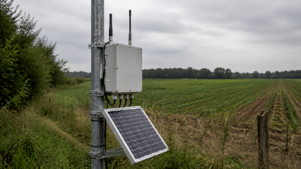
Team som placerar ut småceller och backhaul-reläer på åsar, silor, master och andra platser utanför räckvidden för en tillförlitlig elnätsanslutning.
Offentliga och privata program som utökar kommunikationstäckningen där en nätanslutning är långsammare eller dyrare än en lokal solenergiplattform.
Operatörer som driver privata LTE-nät, mesh-baserad backhaul eller fjärrkommunikationsinfrastruktur över stora och svårtillgängliga områden.
Team som driver LoRaWAN-, NB-IoT- och industriella mobilgatewayer som samlar in data från många vilande noder men måste vara uppkopplade utan avbrott.
Kontinuerlig belastning
Elektrisk arkitektur
Fälttillgänglighet
Inköp och kvalitetssäkring
Referensarkitektur
| Webbplatstyp | Driftcykel | Vad styr storleken |
|---|---|---|
| Hydrologisk nod eller vädernod | ||
| Branddetekteringskamera | ||
| Telekomrelä eller gateway |
| Blockering | Typisk planeringsspecifikation | Varför det är viktigt på en telekomwebbplats |
|---|---|---|
| Solcellsanläggning | ||
| Batteribank | ||
| Laddningsregulator | ||
| Kraftkapsling | ||
| Skyddade utdata | ||
| Fjärrövervakning |
Typiska konfigurationer som planeringsreferens; den slutliga dimensioneringen beror på plats- och belastningsdata.
| Scenario | Referenslösning | Panel och konstruktion | Förväntat resultat |
|---|---|---|---|
| Industriell mobilnäts- eller LoRaWAN-gateway | Börja ovanför den ungefärliga beräkningen för 100 W vid klar himmel och utvärdera den lägre delen av planeringsintervallen för arrayen på 200–800 W och batteriet på 100–400 Ah efter att hänsyn tagits till autonomi, solinstrålning under den sämsta månaden, temperatur- och omvandlingsförluster. | Ett planeringsunderlag för gatewaysajter. Den slutliga dimensioneringen beror på modemets anslutningsstatus, gatewayens bearbetningsbelastning, radions sändningsbeteende, klimatet och tillgänglighetsmålet. | |
| Trådlöst ISP-relä med 24 V-radio | Utvärderas normalt inom mitten av planeringsintervallen på 200–800 W för solcellspanelen och 100–400 Ah för batteriet, med en inbyggd 24 V-arkitektur där det är kompatibelt, MPPT-laddning, separata säkrade utgångar, överspänningsskydd och en vindklassad konstruktion. | Undviker ett onödigt 12 V-booststeg och gör radioingång, kabelförlust, autonomi och synlighet för fjärrunderhåll uttryckliga i den godkända specifikationen. | |
| Liten cell med belastningar för platsstöd | Dimensionera mot den övre delen av planeringsintervallen 200–800 W och 100–400 Ah, eller över dessa när den uppmätta belastningen, den dåliga solinstrålningen vintertid, lång autonomi eller termisk reglering kräver det. Bekräfta nominell batteribanksspänning, toppström, värme i skåpet och monteringsbelastningar. | En specialutvecklad plattform snarare än ett universellt kit. Makrotornssystem med effekt i kilowattklass och generatorhybridsystem ligger fortfarande utanför detta användningsområde. |
Anmäl dig för exklusiva uppdateringar,
nya produkter & rabatter endast för insiders


